Laser thickness gauge taking laser as light source

A thickness gauge and laser technology, applied in the field of measurement, can solve the problems of non-coincidence of measurement points, unstable measurement accuracy, and low measurement accuracy, and achieve the effects of high measurement accuracy, stable operation, and simple installation and use

Active Publication Date: 2013-10-23
谢逢春
View PDF8 Cites 13 Cited by
  • Summary
  • Abstract
  • Description
  • Claims
  • Application Information

AI Technical Summary

Problems solved by technology

[0003] The current laser thickness gauge is generally composed of two laser displacement sensors. Due to the limitation of the working environment in the industrial production line, there will be high temperature in some workplaces, and once the U-shaped frame is deformed or vibrated, th

Method used


Image

  • Laser thickness gauge taking laser as light source

Examples


Embodiment Construction

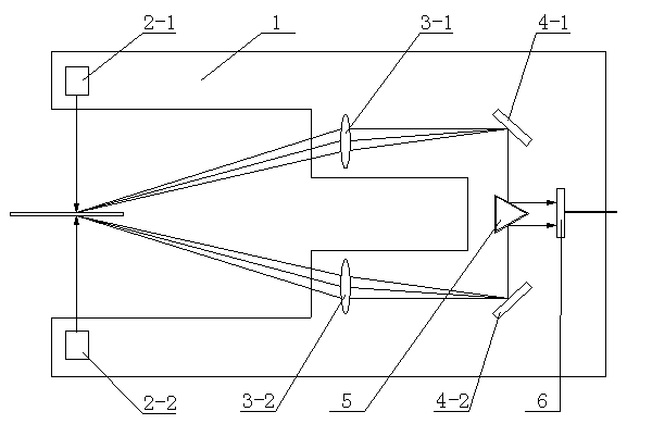
[0014] A laser thickness gauge using a laser as a light source. The structure includes a housing. The key is: a lying U-shaped bracket 1 is arranged on the housing, and a relatively emitting upper laser 2 is arranged in the U-shaped bracket 1- 1 and the lower laser 2-2, non-diffraction optical system, and area array CCD6. The upper surface and the lower surface, and form two upper and lower light spots, the light of these two light spots is imaged on the area array CCD6 through the non-diffraction optical system, and then sent to the computer for processing after photoelectric conversion, and the thickness of the measured object can be directly obtained .

[0015] The structure of described non-diffractive optical system comprises upper lens 3-1, lower lens 3-2, upper reflection mirror 4-1, lower reflection mirror 4-2 and reflection prism 5, wherein upper lens 3-1, upper reflection The mirror 4-1, the lower lens 3-2, and the lower reflector 4-2 are symmetrically arranged up a...


PUM

PropertyMeasurementUnit
Thicknessaaaaaaaaaa
Taperaaaaaaaaaa

Abstract

The invention relates to a laser thickness gauge taking laser as a light source. The laser thickness gauge structurally comprises a shell and is characterized in that a lying U-shaped bracket is arranged on the shell, and an upper laser and a lower laser which are opposite for emitting, a diffraction-free optical system and an area array CCD (Charge Coupled Device) are arranged in the U-shaped bracket. On this basis, laser beams emitted from the upper laser and the lower laser are respectively radiated onto the upper surface and the lower surface of a tested object through the laser thickness gauge to form an upper light spot and a lower light spot; and light rays of the two light spots are imaged onto the area array CCD through the diffraction-free optical system, are subjected to photoelectric conversion and are then transmitted to a computer to be processed to directly obtain the thickness of the tested object. The laser thickness gauge disclosed by the invention has the beneficial effects that the measurement precision is high and reaches +/-0.0015mm, measurement errors caused by deformation, vibration and the like of the U-shaped bracket are avoided, the measurement precision is greatly improved; and the laser thickness gauge is resistant to vibration, simple to install and use, and stable in work.

Description

technical field [0001] The invention belongs to the technical field of measurement, relates to an object capable of measuring thickness below 5mm, and is widely used in various industrial productions that need to measure the thickness of ultra-thin objects. Background technique [0002] The successful application of laser thickness measurement system in non-contact and online dynamic measurement in industrial production plays a very important role in improving product quality, production efficiency and safety guarantee. It can complete many detection tasks that cannot be completed by contact measurement means. Widely used in online dynamic non-contact thickness measurement of battery pole pieces, used in transparent film / paper / glass / rubber cow felt and other production enterprises, used for online detection of product thickness on the production line, used in steel plate, copper / aluminum foil, plate production Enterprises, on-line detection of the thickness of products on t...

Claims


Application Information

Patent Timeline
IPC IPC(8): G01B11/06
Inventor 谢逢春
Owner 谢逢春
Why Eureka
Try Eureka