Material mechanical property in-situ three-point bending test platform with adjustable test environment temperature

A technology of material mechanics and testing environment, applied in the direction of applying stable bending force to test the strength of materials, analyzing materials, strength characteristics, etc., can solve the problem of not considering the influence of temperature field on material properties, and not involving the in-situ microscopic imaging system Observation, not involved in the study of mechanical properties and other issues, to achieve the effect of compact structure, simple structure and convenient control

Active Publication Date: 2013-10-23
JILIN UNIV
View PDF4 Cites 15 Cited by
  • Summary
  • Abstract
  • Description
  • Claims
  • Application Information

AI Technical Summary

Problems solved by technology

However, traditional bending testing machines are mostly aimed at large-scale test pieces at room temperature, and do not involve the study of the mechanical properties of samples in the micro-nano scale, nor do they consider the influence of the temperature field on material properties, and most of them belong to off-site tests. In situ observation to the corresponding microscopic imaging system
The current development of in-situ test devices mainly has the following characteristics: (1) In terms of the compatibility between the test device and the imaging system, due to the limited cavity space of scanning electron microscopes, transmis

Method used


Image

  • Material mechanical property in-situ three-point bending test platform with adjustable test environment temperature
  • Material mechanical property in-situ three-point bending test platform with adjustable test environment temperature
  • Material mechanical property in-situ three-point bending test platform with adjustable test environment temperature

Examples


Embodiment Construction

[0026] The detailed content of the present invention and its specific implementation will be further described below in conjunction with the accompanying drawings.

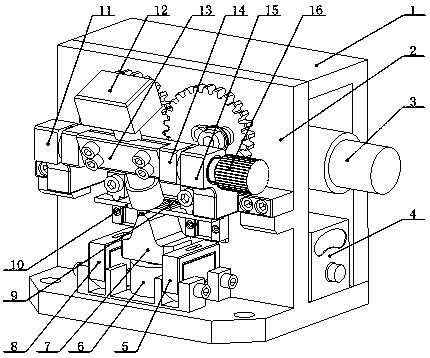
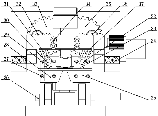
[0027] see Figure 1 to Figure 4 As shown, the in-situ three-point bending test platform for material mechanical properties with adjustable test environment temperature of the present invention includes a precision drive transmission unit, a detection unit, an imaging system unit, a temperature field control unit, and an auxiliary support unit. In-situ real-time dynamic observation of microstructure morphology, lattice changes, crack initiation and expansion under the action of electric field;

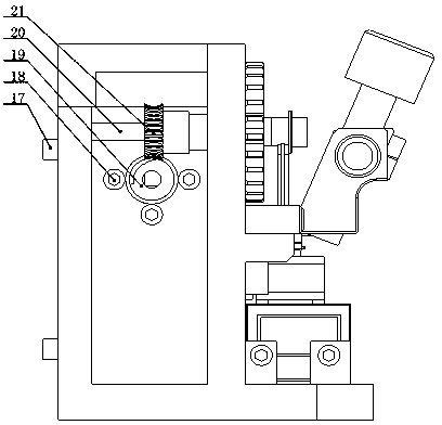
[0028] The precision drive transmission unit is composed of a DC motor 3, a shaft 20, a worm 19 and a worm wheel 21, wherein the DC motor 3 is fastened on the frame 2 by screws II 18, the output shaft of the motor 3 is fixedly connected with the worm 19, and the worm wheel 21 decelerates and outputs the power to the shaft...


PUM


Abstract

The invention relates to a material mechanical property in-situ three-point bending test platform with adjustable test environment temperature, and belongs to the field of in-situ mechanical property test. Test elements are heated up through resistance wires, and are observed by combining with a high-amplification-factor solid state CCD (charge coupled device) industrial imaging lens, and the microstructure variation as well as micromechanics behaviors of crack production, expanding and the like of materials at different environment temperatures under the bending load effect can be monitored dynamically. The material mechanical property in-situ three-point bending test platform with adjustable test environment temperature provided by the invention mainly comprises a precision driving transmission unit, a detecting unit, an imaging system unit, a temperature field control unit and an auxiliary support unit. The material mechanical property in-situ three-point bending test platform with adjustable test environment temperature has the advantages that the structure is simple and compact, the transmission is stable, and a temperature field and stress field are effectively combined, in-situ observation can be carried out on micro deformation, damage and cracking process of materials under a high-resolution imaging system, and thus a novel test method is provided for revealing the mechanical property and the damage mechanism of materials under different temperature fields.

Description

technical field [0001] The invention relates to the field of in-situ mechanical property testing, and relates to an in-situ three-point bending test platform for material mechanical properties with adjustable test environment temperature. In different temperature fields, the high-magnification solid-state CCD industrial imaging system can be used to dynamically observe the microstructure, lattice changes, crack initiation, expansion and fracture of the test material in real time. The mechanical property testing device provides a brand-new method for testing the mechanical properties of materials based on the temperature field. Background technique [0002] In-situ mechanical performance testing refers to the process of testing the mechanical properties of specimen materials at the micro / nano scale. Microscopic imaging systems such as atomic force microscopes, electron microscopes, and optical microscopes can be used to analyze the microscopic properties of materials under va...

Claims


Application Information

Patent Timeline
IPC IPC(8): G01N3/20G01N3/02
Inventor 赵宏伟程虹丙邵明坤张鹏马志超董晓龙鲁帅韩磊高景佟达
Owner JILIN UNIV
Why Eureka
Try Eureka