Distributed optical fiber testing method for seepage in porous media structures

A technology of distributed optical fiber and porous media, applied in suspension and porous material analysis, permeability/surface area analysis, measurement devices, etc., can solve problems such as immature theory

Active Publication Date: 2016-04-13
HOHAI UNIV
View PDF3 Cites 0 Cited by
  • Summary
  • Abstract
  • Description
  • Claims
  • Application Information

AI Technical Summary

Problems solved by technology

However, the theory of this technology in the application of seepage monitoring is still immature, especially the quantitative relationship model between the temperature rise of optical fiber heating, seepage flow velocity, ambient temperature, and heating power has not been established. It is of great significance to develop seepage monitoring methods and devices

Method used


Image

  • Distributed optical fiber testing method for seepage in porous media structures
  • Distributed optical fiber testing method for seepage in porous media structures
  • Distributed optical fiber testing method for seepage in porous media structures

Examples


Embodiment 1

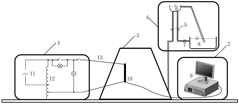
[0050] Embodiment 1: The porous media structure seepage velocity monitoring device based on the total heat transfer coefficient of the present invention, the schematic diagram of the device is as follows figure 1 As shown, it includes a heating system 1, a distributed optical fiber temperature sensing system 2, a porous medium structure model tank 3 embedded with a monitoring optical fiber, and a water outlet system 4; the heating system 1, the distributed optical fiber temperature sensing system 2 and the water outlet system The system 4 is respectively connected with the porous medium structure model tank 3 .

[0051] The heating system 1 is a parallel circuit mainly composed of an AC power supply 11, a voltage regulator 12, and a load heating resistance wire 13. The monitoring optical fiber is heated through the load heating resistance wire 13, and the heating power is controlled by controlling the voltage through the voltage regulator.

[0052] The distributed optical fibe...


PUM


Abstract

The invention discloses a distributed optical fiber test method for porous medium structure seepage, comprising the following steps: (1) constructing a porous medium structure model groove; (2) forming a uniform and stable seepage field; (3) embedding in the model groove (4) Do energized heating operation on the target optical fiber; (5) Measure the temperature rise curve of different heating power under the condition of steady seepage; (6) Construct the heat transfer equation of the total heat transfer coefficient of the optical cable (7) characterize the heat transfer between the optical fiber and the saturated porous medium containing seepage with the total heat transfer coefficient; (8) measure the temperature rise curves of different heating powers under different seepage flow velocities; monitoring. The invention establishes an empirical relational mathematical model of the total heat transfer coefficient of the seepage flow velocity, accurately locates the linear correlation between the seepage flow velocity and the average total heat transfer coefficient, and reliably guarantees the monitoring accuracy.

Description

technical field [0001] The invention relates to a distributed optical fiber test device and method for percolation of a porous medium structure. Background technique [0002] The main problems faced by earth-rock dam projects in my country are leakage, piping, collapse, cracks, landslides, damage to slope protection, erosion and cavitation, etc. According to statistics, more than one-third of the damage in earth-rock dam projects is due to different degrees of seepage Leakage and various problems derived from leakage, more than 90% of embankment collapses are caused by leakage damage. [0003] A large amount of engineering experience shows that it is of great significance to strengthen the real-time positioning and quantitative monitoring of seepage and seepage deformation of earth-rock dams to ensure the safe operation of the project. The seepage problem of earth-rock dams has the characteristics of time-space randomness and concealment, and the initial magnitude is small. ...

Claims


Application Information

Patent Timeline
Patent Type & Authority Patents(China)
IPC IPC(8): G01N15/08G01N25/20G01K11/32G01K11/322G01K11/324
Inventor 苏怀智崔书生杨孟田始光蔡婷婷
Owner HOHAI UNIV
Why Eureka
Try Eureka