Micro-rotor unbalance measurement device and measurement method

A technology of rotor unbalance and measuring device, applied in the field of measurement, can solve the problems affecting the measurement accuracy of vibration displacement signal, vibration response measurement interference, difficult measurement, etc., so as to avoid excessive rotation speed or excessive vibration response, and solve installation problems. , The effect of simple and compact structure

Active Publication Date: 2018-06-15
AERO ENGINE ACAD OF CHINA
View PDF5 Cites 0 Cited by
  • Summary
  • Abstract
  • Description
  • Claims
  • Application Information

AI Technical Summary

Problems solved by technology

The acceleration sensor is a contact measurement, so it cannot be installed on the micro-rotor, but needs to be installed on the base. The vibration response detected by it is the overall response of the micro-rotor and its installation base excited by the unbalance of the micro-rotor. , the response value will be weaker and more difficult to measure
[0006] 2) Interference problem of vibration response measurement
Generally, interference is divided into co-frequency interference, high-frequency interference and low-frequency interference according to frequency. These interference signals greatly increase the complexity and difficulty of later analysis and processing of vibration signals, and also affect the measurement accuracy; optical displacement sensors are used to directly measure micro Compared with the acceleration sensor, the vibration displacement response of the rotor is better immune to the vibration interference of other additional devices, but it still needs to be installed on the support base, and the vibration impact on the support base cannot be avoided
[0007] 3) Installation and impact of measuring equipment
The installation of measuring equipment is mainly for the optical displacement sensor. The axial size of the micro-rotor is small, generally in the order of μm, and rarely in the order of mm. The optical displacement sensor is mainly installed in the radial direction, and the radial direction of the micro-rotor is realized The direct measurement of vibration displacement places extremely high requirements on the size of the sensor and the design of the micro-rotor support structure, and it is very difficult to realize. To solve this problem, MIT adopts the method of machining the measuring boss on the axial end surface of the micro-rotor, through The axially installed optical displacement sensor monitors the measuring boss, and then indirectly analyzes the radial vibration displacement of the micro-rotor through a set of extremely complex signal data processing and analysis programs. The complex data processing in this indirect measurement method will also affect the vibration displacement. Signal Measurement Accuracy

Method used


Image

  • Micro-rotor unbalance measurement device and measurement method
  • Micro-rotor unbalance measurement device and measurement method
  • Micro-rotor unbalance measurement device and measurement method

Examples


Embodiment Construction

[0042] The present disclosure will be further described in detail below in conjunction with the accompanying drawings and embodiments. It should be understood that the specific embodiments described here are only used to explain relevant content, rather than to limit the present disclosure. It should also be noted that, for ease of description, only parts related to the present disclosure are shown in the drawings.

[0043] It should be noted that, in the case of no conflict, the embodiments in the present disclosure and the features in the embodiments can be combined with each other. The present disclosure will be described in detail below with reference to the accompanying drawings and embodiments.

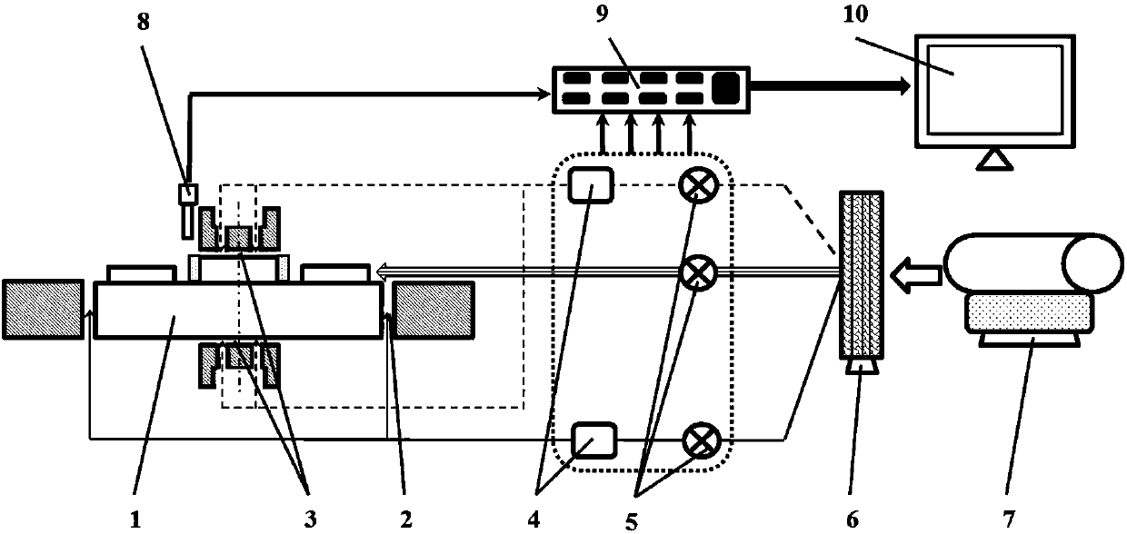
[0044] The micro-rotor unbalance measurement device includes a static pressure radial gas bearing 2, a static pressure thrust gas bearing 3, an optical fiber displacement sensor 8 and a data acquisition card 9;

[0045] The static pressure radial gas bearing 2 is used for the ...


PUM


Abstract

The invention provides a micro-rotor unbalance measurement device which comprises a static-pressure radial gas bearing, a static-pressure thrust gas bearing, an optical fiber displacement sensor and adata acquisition card; the static-pressure radial gas bearing is used for the radial support of the micro-rotor to be tested; the static-pressure thrust gas bearing is used for the axial support of the micro-rotor to be tested; the optical fiber displacement sensor is used for measuring the rotating speed of the micro-rotor to be tested; and the data acquisition card is used for collecting voltage signals output by the optical fiber displacement sensor.

Description

technical field [0001] The present disclosure relates to the field of measurement technology, in particular to a micro-rotor unbalance measurement device and measurement method. Background technique [0002] Limited by the micro-machining process, it is difficult for the center of gravity and the geometric center of the micro-rotor to completely coincide. The offset of the center of gravity or the amount of weight applied at a certain radius for balance is the unbalance amount. Micro-rotors are small in size, light in weight, and small in length-to-diameter ratio (micro-rotor axial length L / micro-rotor diameter D≤0.1). Stable work at ultra-high speed. The existence of unbalance will lead to the increase of the limit eccentricity of the micro-rotor when the critical speed exceeds the critical speed, and the increase of the amplitude of the ultra-high-speed rotational vibration, which has a serious impact on the dynamic characteristics of the micro-rotor, especially the stabi...

Claims


Application Information

Patent Timeline
Patent Type & Authority Applications(China)
IPC IPC(8): G01M1/16
CPCG01M1/16
Inventor 陈霞闫晓军张学宁
Owner AERO ENGINE ACAD OF CHINA
Why Eureka
Try Eureka