Supercharge Your Innovation With Domain-Expert AI Agents!

Method for adjusting the position of a supporting element in a particle beam device

A technology of support components and particle beams, which is applied to electrical components, irradiation devices, discharge tubes, etc., and can solve problems such as undesired movement of test benches

Active Publication Date: 2013-10-23
CARL ZEISS MICROSCOPY GMBH
View PDF4 Cites 0 Cited by
  • Summary
  • Abstract
  • Description
  • Claims
  • Application Information

AI Technical Summary

Problems solved by technology

This causes additional undesired movement and puts the test bench in an undesired position

Method used


Image

  • Method for adjusting the position of a supporting element in a particle beam device
  • Method for adjusting the position of a supporting element in a particle beam device
  • Method for adjusting the position of a supporting element in a particle beam device

Examples


Embodiment Construction

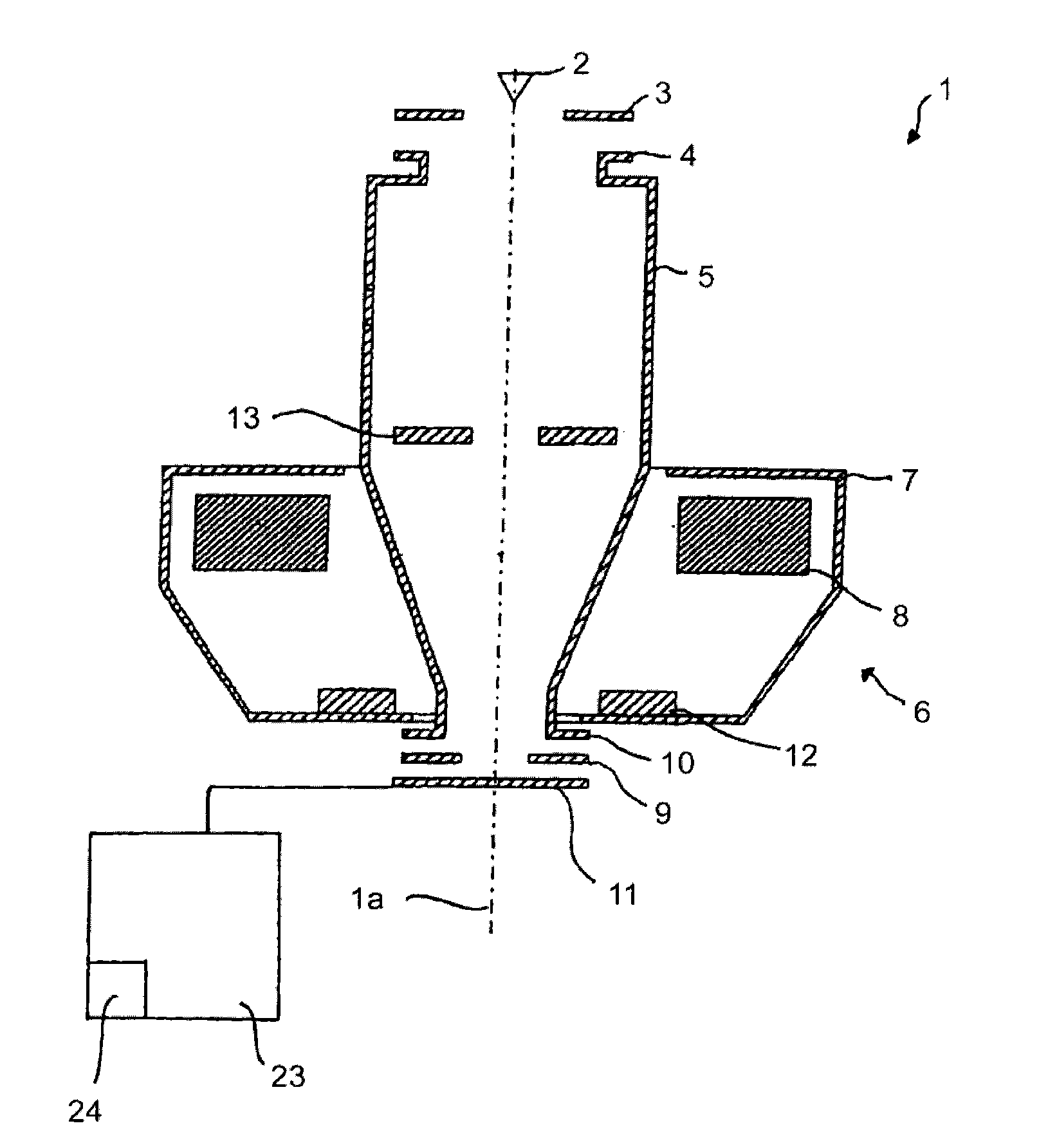
[0047] figure 1 A schematic diagram of a particle beam column 1 of a particle beam device is shown, which is designed as an electron beam column and essentially corresponds to an electron beam column of a scanning electron microscope. However, it is expressly pointed out here that the invention is not limited to scanning electron microscopes. Rather, the present invention can be used in various particle ray devices, particularly in ion beam devices.

[0048] The particle beam column 1 has an optical axis 1 a, a beam generator in the form of an electron source 2 (cathode), a extraction electrode 3 and an anode, which simultaneously form the end of a beam guide 5 . For example the electron source 2 is a thermal field emitter. Electrons emitted from the electron source 2 are accelerated towards the anode potential due to the potential difference between the electron source 2 and the anode 4 . This provides a particle beam in the form of an electron beam.

[0049]Furthermore, ...


PUM


Abstract

The invention relates to a method for adjusting the position of a supporting element installed in a particle beam device. The supporting element is designed for supporting an object. The particle beam device comprises at least one beam generator used for a particle beam and at least one objective lens used for focusing the particle beam. The supporting element is designed to be moved by means of at least one first stepping motor. The method comprises following steps: starting a movement of the supporting element by controlling and manipulating the first stepping motor with first motor current used as alternate current; adjusting the first motor current to a first frequency and a first amplitude; stopping the movement of the supporting element by reducing the frequency and the amplitude of the first motor current, wherein the first frequency is reduced to zero in a predetermined period and the amplitude is reduced to the amplitude of first predetermined holding current in the first predetermined period.

Description

technical field [0001] The invention relates to a method for adjusting the position of a support element arranged in a particle beam system. In this case, the carrier element is designed, for example, as a movably arranged test stand, on which the sample (object) to be examined and / or processed is placed. Background technique [0002] Particle beam systems are known from the prior art, for example scanning electron microscopes or ion beam systems with a bench on which an object to be examined and / or processed is arranged. The test stand is designed to be movable, wherein the movable design of the test stand is ensured by a plurality of moving elements from which the test stand is assembled. These moving elements enable the test bench to move in at least one defined direction. In particular, test benches are known which have a plurality of translational movement elements (eg approximately 3 to 4 translational movement elements) and a plurality of rotational movement element...

Claims


Application Information

Patent Timeline
Patent Type & Authority Applications(China)
IPC IPC(8): H01J37/26H01J37/20H01J37/28H02P8/40
CPCH01J2237/20221H02P8/40H01J2237/28G21K5/10H01J2237/20285H01J2237/20214H01J37/20
Inventor M·克纳皮奇
Owner CARL ZEISS MICROSCOPY GMBH
Features
  • R&D
  • Intellectual Property
  • Life Sciences
  • Materials
  • Tech Scout
  • Unparalleled Data Quality
  • Higher Quality Content
  • 60% Fewer Hallucinations
Learn More