Supercharge Your Innovation With Domain-Expert AI Agents!

Signal encoder simulation method

A simulation method and encoder technology, which is applied in the field of motor mover orientation detection signal encoder simulation, can solve the problems of high cost, inconvenient test operation, and lack of efficiency

Inactive Publication Date: 2013-10-23
宣玮电机有限公司
View PDF0 Cites 0 Cited by
  • Summary
  • Abstract
  • Description
  • Claims
  • Application Information

AI Technical Summary

Problems solved by technology

In this existing method, the motor needs to provide an angle signal to the electronic gear (synchronous), and can only output pulse (Pulse), and it is fixed, not only the test operation is quite inconvenient, inefficient, but also the cost is high

Method used


Image

  • Signal encoder simulation method
  • Signal encoder simulation method
  • Signal encoder simulation method

Examples


Embodiment Construction

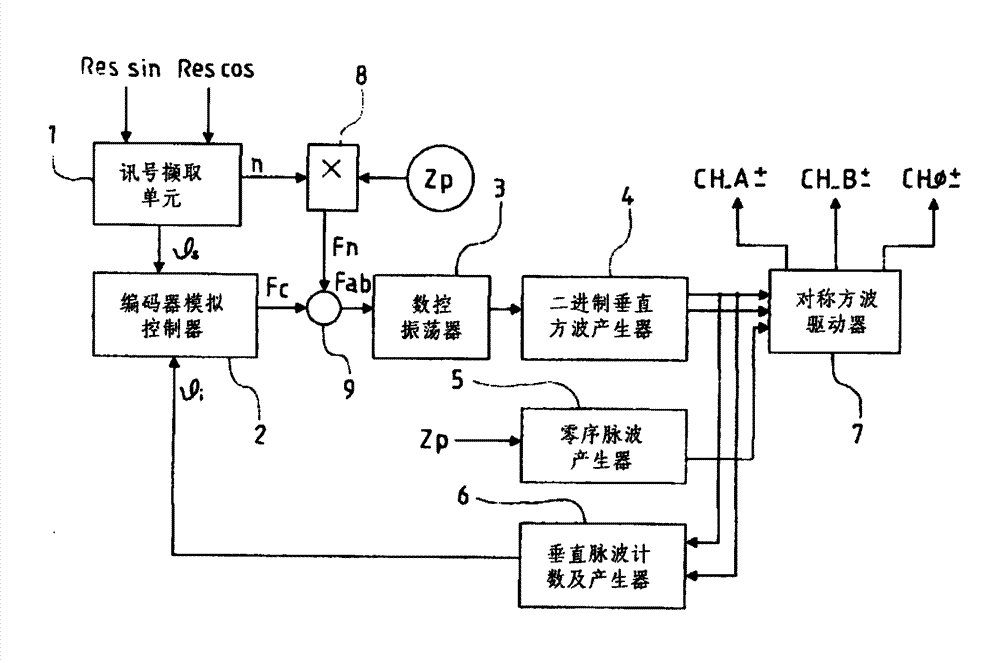
[0028] see figure 1 Shown is a circuit block diagram of a preferred embodiment of the present invention. As shown in the figure, the present invention includes a signal acquisition unit 1, an encoder analog controller 2, a digitally controlled oscillator 3, a binary vertical square wave generator 4, a zero-sequence pulse wave generator 5, and a vertical pulse wave counter and generator 6 And symmetrical square wave driver 7. Among them, the signal acquisition unit 1 is used to extract the sin and cos signals of components such as servo motors, and convert the sin and cos signals into speed signals (n) and angle signals The speed signal is connected to a multiplier 8 to form a multiplied speed signal (Fn) and a reset signal (Zp), and the angle signal is sent to the encoder analog controller 2, which is generated by the encoder analog controller 2 Correction frequency (Fc);

[0029] The multiplied speed signal (Fn) formed by the multiplier 8 is added to the correction freque...


PUM


Abstract

A signal encoder simulation method comprises: acquiring the sin and the cos signals of elements such as a servo motor and the like and transforming the sin and the cos signals into a speed signal and an angle signal; forming an addition and multiplication speed signal and a reset signal from the speed signal and converting the angle signal into a rectification frequency; adding the addition and multiplication speed signal to the rectification frequency; and generating a binary digital signal, further generating a binary vertical square wave from the binary digital signal, and outputting a pulse signal forever maintaining 90 degrees and a zero signal so as to facilitate the detection of a motor mover orientation. By using the provided method, the pulse signal forever maintaining 90 degrees and the zero signal are outputted so that the detection of the motor mover orientation can be adjustable for motors of different types.

Description

technical field [0001] The invention relates to a method for simulating a signal encoder, in particular to a method for simulating a signal encoder capable of outputting a pulse signal and a 0 signal that are always maintained at 90°, so as to facilitate detection of the position of a motor mover. Background technique [0002] The general method of detecting the position of the motor mover is to install an encoder on the motor, and use the peak value detection to find out the position and obtain the signal. In this existing method, the motor needs to provide an angle signal to the electronic gear (synchronous), and can only output pulses (Pulse), and it is fixed, which is not only inconvenient for test operation, but also lacks efficiency and high cost. In view of this, the applicant, based on years of experience in this business, through continuous research and experiments, designed a signal encoder simulation method so that the pulse signal and zero signal that are always ...

Claims


Application Information

Patent Timeline
Patent Type & Authority Applications(China)
IPC IPC(8): H02P6/06H02P6/16
Inventor 邓庭蓁
Owner 宣玮电机有限公司
Features
  • R&D
  • Intellectual Property
  • Life Sciences
  • Materials
  • Tech Scout
  • Unparalleled Data Quality
  • Higher Quality Content
  • 60% Fewer Hallucinations
Learn More