
Video noise reduction device and video noise reduction method

A video noise reduction and noise reduction technology, which is applied in the direction of TV, color TV, color TV parts, etc., can solve the problems of serious noise in infrared images, blurred edges, and inability to obtain better denoising results

Active Publication Date: 2013-10-23
SHANGHAI TONGTU SEMICON TECH
View PDF3 Cites 44 Cited by
  • Summary
  • Abstract
  • Description
  • Claims
  • Application Information

AI Technical Summary

Problems solved by technology

For example, there are many interference factors in the infrared image during the imaging process, which makes the infrared image noisy and the edges blurred
General denoising methods, such as mean filter, median filter, Wiener filter and wavelet soft and hard threshold method, etc., cannot achieve better denoising results.

Method used


Image

  • Video noise reduction device and video noise reduction method
  • Video noise reduction device and video noise reduction method
  • Video noise reduction device and video noise reduction method

Examples


Embodiment Construction

[0103] The implementation of the present invention is described below through specific examples and in conjunction with the accompanying drawings, and those skilled in the art can easily understand other advantages and effects of the present invention from the content disclosed in this specification. The present invention can also be implemented or applied through other different specific examples, and various modifications and changes can be made to the details in this specification based on different viewpoints and applications without departing from the spirit of the present invention.

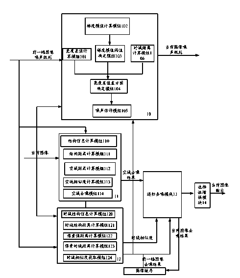
[0104] figure 1 It is a system architecture diagram of a video noise reduction device of the present invention. Such as figure 1 As shown, a video noise reduction device of the present invention can be used to denoise complex and strong noise (such as infrared image noise) in video images, which at least includes: noise level estimation module 10, spatial similarity denoising module 11, T...


PUM


Abstract

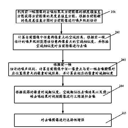
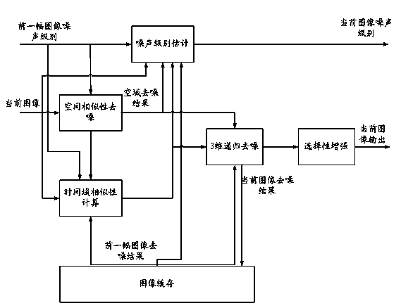
The invention discloses video noise reduction device and a video noise reduction method. The method comprises the following steps of: obtaining a brightness difference histogram of a current image by using a denoising result of a previous frame of image and a gradient magnitude histogram of the current image; carrying out noise level evaluation on the current image according to the brightness difference histogram; calculating the spatial distance of any two pixel points in the current image, so as to obtain the spatial similarity of the any two pixel points; carrying out denoising on the current image according to the spatial similarity; calculating a pixel time domain distance between any pixel point in the current image and the pixel point at the position corresponding to the previous frame of denoised image, and calculating the corresponding time domain similarity; carrying out three-dimensional recursive denoising on the video image according to the obtained time domain similarity, the spatial similarity denoising result and the previous frame of denoising result. By adopting the device and method disclosed by the invention, three-dimensional recursive denoising is carried out by using the pertinence of the pixel in space and time, so that strong complicated noise can be removed; an image detail can be kept; the stability of the denoising effect also can be ensured.

Description

technical field [0001] The present invention relates to a video noise reduction device and method, in particular to a video noise reduction device and method based on pixel similarity. Background technique [0002] Video noise reduction has always been one of the hotspots in image and video processing and computer vision research. The direct purpose of image and video denoising is to improve the noise-contaminated video image and solve the problem of image quality degradation caused by noise interference in actual images. Denoising can effectively improve the video image quality, increase the signal-to-noise ratio, and better reflect the information carried by the original video. A good denoising method will also improve the quality of subsequent video image processing, such as object segmentation, edge extraction, object tracking and recognition, etc. [0003] The key to denoising is to remove the interfering information in the signal while maintaining the integrity of us...

Claims


Application Information

Patent Timeline
IPC IPC(8): H04N5/21G06T5/00
Inventor 林江查毓水
Owner SHANGHAI TONGTU SEMICON TECH
Learn More