
Internet-of-things fire monitoring system based on cloud services

A technology of fire monitoring and Internet of Things, which is applied in transmission systems, fire alarms, instruments, etc., can solve problems such as difficult to meet the requirements of fire protection equipment management, different scales, and multiple capital investments, so as to improve the production level of fire safety, The effect of saving capital investment and improving management efficiency

Inactive Publication Date: 2013-10-30
WANSENT CHINA TECH
View PDF0 Cites 18 Cited by
  • Summary
  • Abstract
  • Description
  • Claims
  • Application Information

AI Technical Summary

Problems solved by technology

Although these systems have solved the management problems of some fire alarm equipment to a certain extent, due to the lack of unified standards, the operating units of each monitoring center are different, the scales are different, and the technologies used are different, making it difficult for each monitoring center. To achieve interconnection, each center becomes an isolated island of information, unable to obtain comprehensive information on the operation status of fire protection equipment, and provides fewer services to users. This model requires more capital investment and higher operating costs in the initial stage. great difficulty
In addition, the main purpose of the traditional remote monitoring system for fire protection equipment is to provide the fire management department with real-time information on the operation of fire protection equipment in various buildings, while seldom considering the services for fire protection equipment users. This model lacks long-term financial support and development loses momentum
Due to the above problems, it is difficult for the current fire network system put into use to meet the requirements of all parties for the management of fire protection equipment.

Method used


Image

  • Internet-of-things fire monitoring system based on cloud services
  • Internet-of-things fire monitoring system based on cloud services
  • Internet-of-things fire monitoring system based on cloud services

Examples


Embodiment Construction

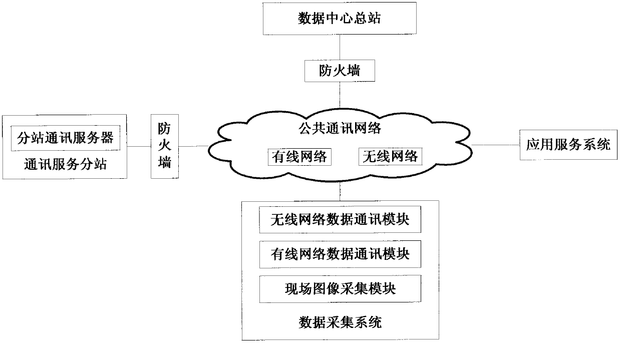
[0021] like figure 1 , figure 2 As shown, the Internet of Things fire monitoring system based on cloud services includes the data center main station, communication service sub-station, data acquisition system and application service system; the communication service sub-station, data acquisition system and application service system communicate with the data center through the public communication network Terminus connection. The public communication network includes GPRS, CDMA, 3G and other existing wireless communication methods such as wireless networks and wired networks.

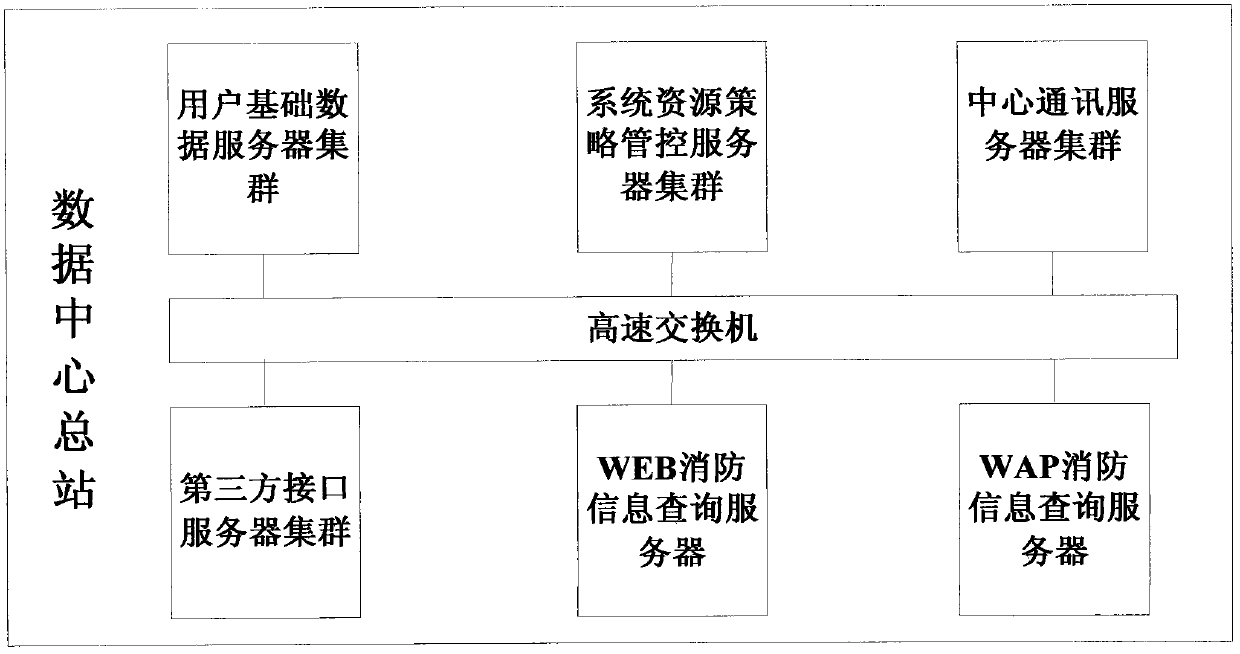
[0022] The data center main station is placed in a data center computer room in the form of hosting servers. The data center should have three or more network access capabilities, be located on the Internet backbone network, have good bandwidth and network speed conditions, and be able to provide several fixed IP addresses. In order to improve the reliability and security of the operation of the da...


PUM


Abstract

The invention discloses an internet-of-things fire monitoring system based on cloud services. The internet-of-things fire monitoring system comprises a data center master station, communication service slave stations, a data acquisition system and an application service system, wherein the communication service slave stations, the data acquisition system and the application service system are connected with the data center master station by a public communication network. The internet-of-things fire monitoring system disclosed by the invention provides one-stop service of real-time monitoring of fire-fighting facilities, installation and maintenance of equipment, fire-fighting consultation and daily fire-fighting safety management by applying technologies such as internet of things, cloud computation and expert systems and integrating a conventional urban fire-fighting networking monitoring system.

Description

technical field [0001] The invention relates to the technical field of fire remote monitoring systems, in particular to a cloud service-based Internet of Things fire monitoring system. Background technique [0002] Nowadays, in large and medium-sized buildings and public places in cities, automatic fire alarm systems and fire-fighting facilities are quite popular, and fire warning can be achieved to a certain extent. In order to further shorten the fire detection and alarm time, reduce the occurrence of fires, take effective fire prevention and fire extinguishing measures in time, improve the reliability of the automatic fire alarm system and reduce false alarms, the networking and monitoring technology of the automatic fire alarm system has become the development trend in the field of fire detection and alarm. new hotspot. However, since these automatic alarm systems are basically independently purchased and installed and work independently, there are problems such as non-...

Claims


Application Information

Patent Timeline
IPC IPC(8): A62C37/00G08B17/00H04L12/28H04L29/06H04L29/08
Inventor 经纬
Owner WANSENT CHINA TECH
Features
  • Generate Ideas
  • Intellectual Property
  • Life Sciences
  • Materials
  • Tech Scout
  • Unparalleled Data Quality
  • Higher Quality Content
  • 60% Fewer Hallucinations
Learn More