Two-stage water inlet weir plate

A water inlet weir and weir plate technology, which is applied in the direction of gravity filter, loose filter material filter, filtration separation, etc., can solve the problem of large inflow flow changes, water head loss, stainless steel or plastic water inlet weir plate is not uniform Water distribution and other problems, to achieve the effect of reducing flow rate, improving performance and reducing dissolved oxygen

Inactive Publication Date: 2013-10-30
居国文
View PDF4 Cites 5 Cited by
  • Summary
  • Abstract
  • Description
  • Claims
  • Application Information

AI Technical Summary

Problems solved by technology

[0003] As a fluid, the water enters the filter from one end of the filter, first flows along the inlet channel in the pool from the water inlet to the discharge end, until the water level in the inlet channel in the pool rises to the top of the weir, and then turns over the inlet weir and weir plate to enter the filter 1, The process of water flowing from the inlet end of the inlet channel in the pool to the outlet end rubs against the inner wall of the inlet channel along the way. At the same time, there are factors such as turbulence in the water flow, which causes head loss. The water level in the inlet channel in the pool is not completely horizontal. The inlet weir is a concrete structure, and stainless steel or Plastic water inlet weir plate, the upper edge of the concrete structure water inlet weir is horizontal, and then the uniformity of water inflow is controlled by adjusting the levelness of the stainless steel or plastic water inlet weir plate. The stainless steel or plastic water inlet weir plate currently installed is single The installation and adjustment requirements of the single-stage water inlet weir plate and the single-stage water inlet weir plate are very high, but due to the large change of the inflow flow, usually the installed and adjusted stainless steel or plastic water inlet weir plate cannot evenly distribute water

Method used


Image

  • Two-stage water inlet weir plate
  • Two-stage water inlet weir plate
  • Two-stage water inlet weir plate

Examples


Embodiment Construction

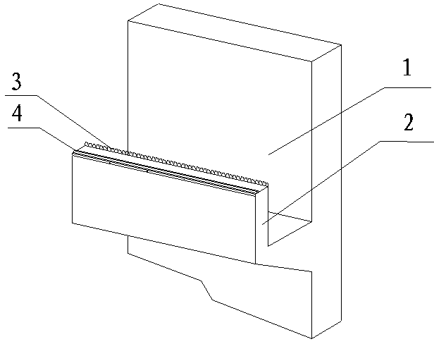
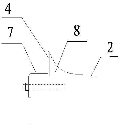
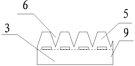
[0011] Such as figure 1 As shown, a two-stage water inlet weir plate includes a water inlet channel 1, and a water inlet weir 2 is provided on the water inlet channel 1. It is characterized in that a flow control weir plate 3 is provided on the inner side of the water inlet weir 2, The outer edge of the water inlet weir 2 is provided with a uniform water distribution weir plate 4 . Such as figure 2 As shown, the flow control weir plate 3 includes a base 9, on which several trapezoidal teeth 5 are arranged, and a weir opening 6 is arranged between two adjacent trapezoidal teeth 5, and the weir opening 6 is V-shaped, and the V-shaped weir opening 6 The trapezoidal teeth on both sides are hollowed out. Such as image 3 As shown, the uniform water distribution weir plate 4 is composed of a support 7 and a weir plate 8. The support 7 fixes the weir plate 8 on the outer edge of the water inlet weir 2. The weir plate 8 is arc-shaped, and the inner side of the weir plate 8 for th...


PUM


Abstract

The invention discloses a two-stage water inlet weir plate. The two-stage water inlet weir plate comprises a water inlet channel (1); the water inlet channel (1) is provided with a water inlet weir (2); an inner upper edge of the water inlet weir (2) is provided with a flow control weir plate (3); an outer upper edge of the water inlet weir (2) is provided with a uniform water distribution weir plate (4); the flow control weir plate (3) comprises a pedestal (9); stepped teeth (5) are arranged on the pedestal (9); a weir port (6) is arranged between two adjacent stepped teeth (5); the uniform water distribution weir plate (4) comprises a bearer (7) and a weir plate (8); the bearer (7) fixes the weir plate (8) on the outer upper edge of the water inlet weir (2). According to the two-stage water inlet weir plate provided by the invention, the first stage is a flow control weir plate for controlling inlet water, so that each point on the length direction of the water inlet weir has inlet water passing over the water inlet weir; and the second stage is a uniform water distribution weir plate for dispersing inlet water flow, and reducing flow velocity and dissolved oxygen generated by dropping effect.

Description

technical field [0001] The invention relates to a two-stage water inlet weir plate. Background technique [0002] The deep bed three-stage filtration filter and deep bed denitrification filter system adopt a narrow and long pool structure, that is, the filter tank has a large aspect ratio, generally 5:1 to 10:1, and the filter tank width is usually 3 to 4 meters , the length of the filter is 10 to 30 meters, and the inlet channels are arranged on both sides of the filter along the length of the filter. The length is similar to the length of the inlet channel in the pool, that is, the inlet weir is 10 to 30 meters. Since the inlet weir is longer, the performance of the inlet weir plate determines the uniformity of the inlet water distribution. [0003] As a fluid, the water enters the filter from one end of the filter, first flows along the inlet channel in the pool from the water inlet to the discharge end, until the water level in the inlet channel in the pool rises to the...

Claims


Application Information

Patent Timeline
Patent Type & Authority Applications(China)
IPC IPC(8): B01D24/40C02F3/28
Inventor 居国文
Owner 居国文
Why Eureka
Try Eureka