Different-diameter guiding combined cutting tap or combined cutting cone

A compound cutting and tap technology, which is applied in thread cutting tools, thread cutting devices, metal processing equipment, etc., can solve the problems of scrapped workpieces, easy breakage of thread blades, and failure to play a guiding role.

Inactive Publication Date: 2013-10-30
李仕清
View PDF8 Cites 3 Cited by
  • Summary
  • Abstract
  • Description
  • Claims
  • Application Information

AI Technical Summary

Problems solved by technology

[0002] At present, the spiral taps or compound cutting cones or straight flute taps or compound cutting cones used in machining are composed of a thread body and a thread handle, and the thread body is composed of a thread strip and a cutting edge surface, a thread edge, chamfer, The chamfering edge and other components, the thread edge, the cutting edge surface of the chamfering edge is roughly on a curved surface or the same helicoidal surface, and the line connecting the bottom of each thread blade is roughly on a straight line or spiral, because the thread at the chamfer The distance from the top to the bottom of the wire is too small to play a guiding role. As a result, tapping becomes reaming, causing the workpiece to be scrapped. Moreover, since each group of wire edge surfaces is composed of a single surface, when the angle between the cutting edge surface and the wire top If it is too sharp, the thread blade is easy to break. For example, if the angle between the cutting edge surface and the thread top is too large, the torque between the thread handle and the clamping tool is too large, which will easily cause the overall fracture of the tap or the compound cutting cone in the workpiece, resulting in the quality of the workpiece being affected. damaged or scrapped

Method used


Image

  • Different-diameter guiding combined cutting tap or combined cutting cone
  • Different-diameter guiding combined cutting tap or combined cutting cone
  • Different-diameter guiding combined cutting tap or combined cutting cone

Examples


Embodiment approach 1

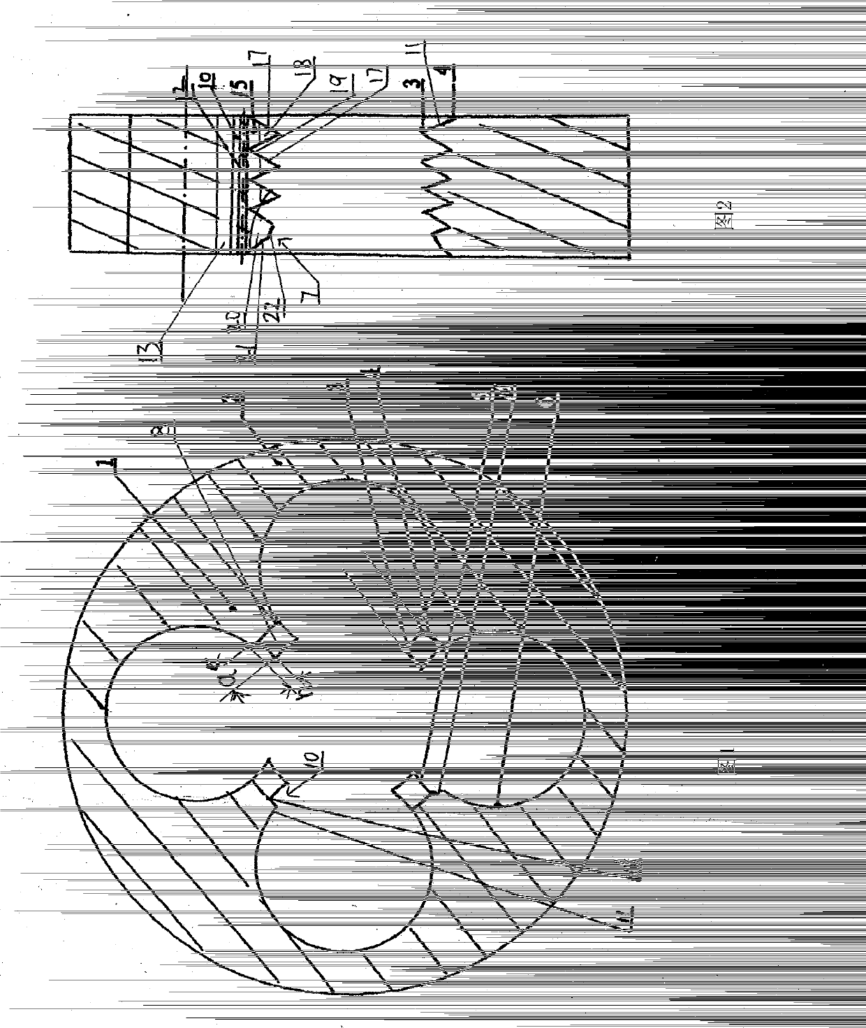
[0044] Such as figure 1 , figure 2 As shown, the split-diameter-guided compound cutting tap or compound cutting cone of the first embodiment includes a tap body 1 and a shell 2 connected or formed as one, and at least one thread body 1 is connected or integrated on the cone, or At least one spiral thread body 1, or at least one taper thread body 1, each thread body has a cutting edge surface 6 at the front of the split-diameter guide compound cutting tap or the axial front end of the compound cutting cone. The side chamfering 8 on the back side of the cutting edge surface 6 is the rear cutting surface 7, the outer surface of the cutting edge surface 6 is the side cutting surface 8, and the cutting edge surface 6 intersects with the rear cutting surface 7 to form a chamfering thread edge 9 , or the cutting edge surface 6 intersects with the side cutting surface 8 to form a cutting wire edge 11, and the diameter of the wire base 3 is The diameter of wire top 4 is It is char...

Embodiment approach 2

[0046] Such as image 3 , Figure 4 As shown, the split-diameter guiding compound cutting tap or compound cutting cone of the second embodiment, on the basis of the technical effect of the first embodiment, the present invention includes a tap body 1 and a casing 2, and the tap body 1 and the casing 2 connected or formed as one, or the taper body 1 and the shell 2, the taper body 1 and the shell 2 are connected or formed as one, at least one thread body 1 is connected or integrated on the tap or the cone, or at least A helical thread cutting body 1, or at least one tapered thread cutting body 1, each thread cutting body has a cutting edge surface 6 at the front end of the split-diameter-guided compound cutting tap or compound cutting cone, at the cutting entry point The surface of the cutting edge surface 6 back side chamfering 8 is the rear cutting surface 7, the surface on the outer side of the cutting edge surface 6 is the side cutting surface 8, and the cutting edge surfa...

Embodiment approach 3

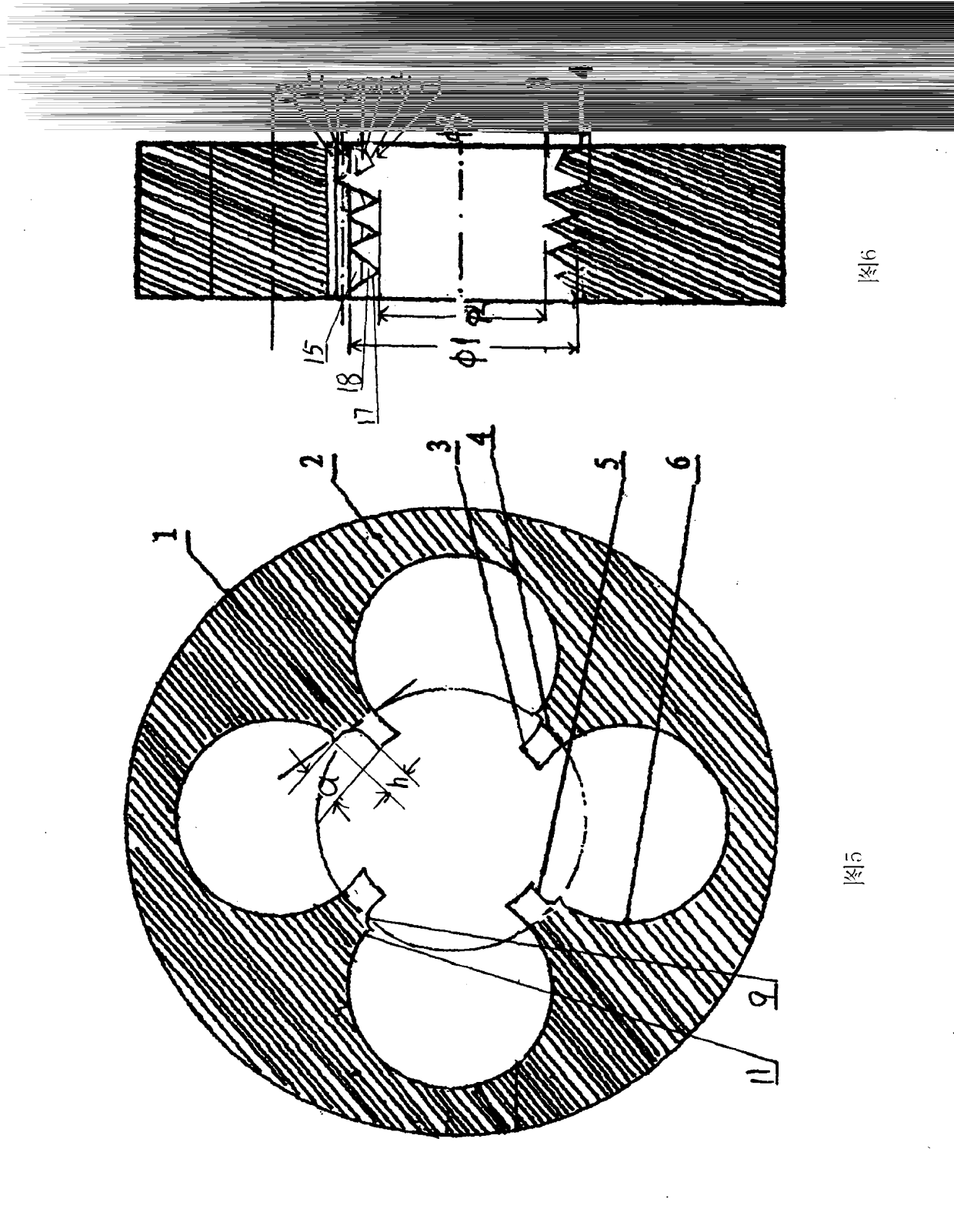
[0048] Such as Figure 5 , Figure 6 As shown, the split-diameter-guided compound cutting tap or compound cutting cone of the third embodiment, on the basis of the technical effects of the first and second embodiments, the present invention includes a tap body 1 and a shell 2, and the tap body 1 is connected or formed as one with the housing 2, or the taper body 1 and the housing 2, the taper body 1 and the housing 2 are connected or formed as one, and at least one thread body 1 is connected or integrated on the tap or the cone , or at least one spiral thread body 1, or at least one taper thread body 1, each thread body has a cutting edge surface 6 at the front of the split-diameter guide compound cutting tap or the axial front end of the compound cutting cone, cutting The side chamfering 8 on the back side of the cutting edge surface 6 at the entry point is the rear cutting surface 7, the outer surface of the cutting edge surface 6 is the side cutting surface 8, and the cutt...


PUM


Abstract

The invention discloses a different-diameter guiding combined cutting tap or combined cutting cone which comprises screw blades and a screw shank. The different-diameter guiding combined cutting tap or combined cutting cone is characterized in that an anti-crack slitting table or anti-crack guided cutting table is arranged on the cutting edge surface of each anti-crack screw blade of the tap or cone, the relationship between the height of each anti-crack slitting table or efficient slitting table and the height of an inside adjacent efficient slitting table is defined as the formula that the heights of the anti-crack slitting table or efficient slitting table and the inside adjacent efficient slitting table are calculated by multiplying a feed amount by a product, the cutting feed amount is small while the multiplied product is large when a workpiece is high in hardness or viscosity while a cutter is large, the cutting feed amount is small while the multiplied product is large when the workpiece is high in hardness or viscosity while the cutter is small, the cutting feed amount is large while the multiplied product is small when the workpiece is low in hardness or viscosity while the cutter is large, and the cutting feed amount is large while the multiplied product is small when the workpiece is low in hardness or viscosity while the cutter is small.

Description

technical field [0001] The invention relates to a split-diameter-guided compound cutting tap or a compound cutting cone, in particular to a split-diameter-guided compound cutting tap or a compound cutting cone. Background technique: [0002] At present, the spiral taps or compound cutting cones or straight flute taps or compound cutting cones used in machining are composed of a thread body and a thread handle, and the thread body is composed of a thread strip and a cutting edge surface, a thread edge, chamfer, The chamfering edge and other components, the thread edge, the cutting edge surface of the chamfering edge is roughly on a curved surface or the same helicoidal surface, and the line connecting the bottom of each thread blade is roughly on a straight line or spiral, because the thread at the chamfer The distance from the top to the bottom of the wire is too small to play a guiding role. As a result, tapping becomes reaming, causing the workpiece to be scrapped. Moreove...

Claims


Application Information

Patent Timeline
Patent Type & Authority Applications(China)
IPC IPC(8): B23G5/06
Inventor 李仕清
Owner 李仕清
Why Eureka
Try Eureka