
A full hydraulic steering system steering wheel angle positioning control device

A steering wheel angle and steering system technology, applied in steering mechanism, fluid steering mechanism, transportation and packaging, etc., can solve the problem of asymmetry of left and right steering flow, achieve simple structure, good reliability, and reduce accidents

Inactive Publication Date: 2016-12-14
SOUTH CHINA UNIV OF TECH
View PDF6 Cites 0 Cited by
  • Summary
  • Abstract
  • Description
  • Claims
  • Application Information

AI Technical Summary

Problems solved by technology

[0003] In order to overcome the shortcomings and deficiencies of the prior art, the present invention provides a full hydraulic steering system steering wheel angle positioning control device, which solves the problem of automatic adjustment and compensation of the asymmetrical error of the left and right steering flow in the steering operation, so that the steering wheel maintains its alignment. Medium performance

Method used


Image

  • A full hydraulic steering system steering wheel angle positioning control device
  • A full hydraulic steering system steering wheel angle positioning control device
  • A full hydraulic steering system steering wheel angle positioning control device

Examples


Embodiment Construction

[0026] The specific embodiments of the present invention will be described in further detail below, but the embodiments of the present invention are not limited thereto.

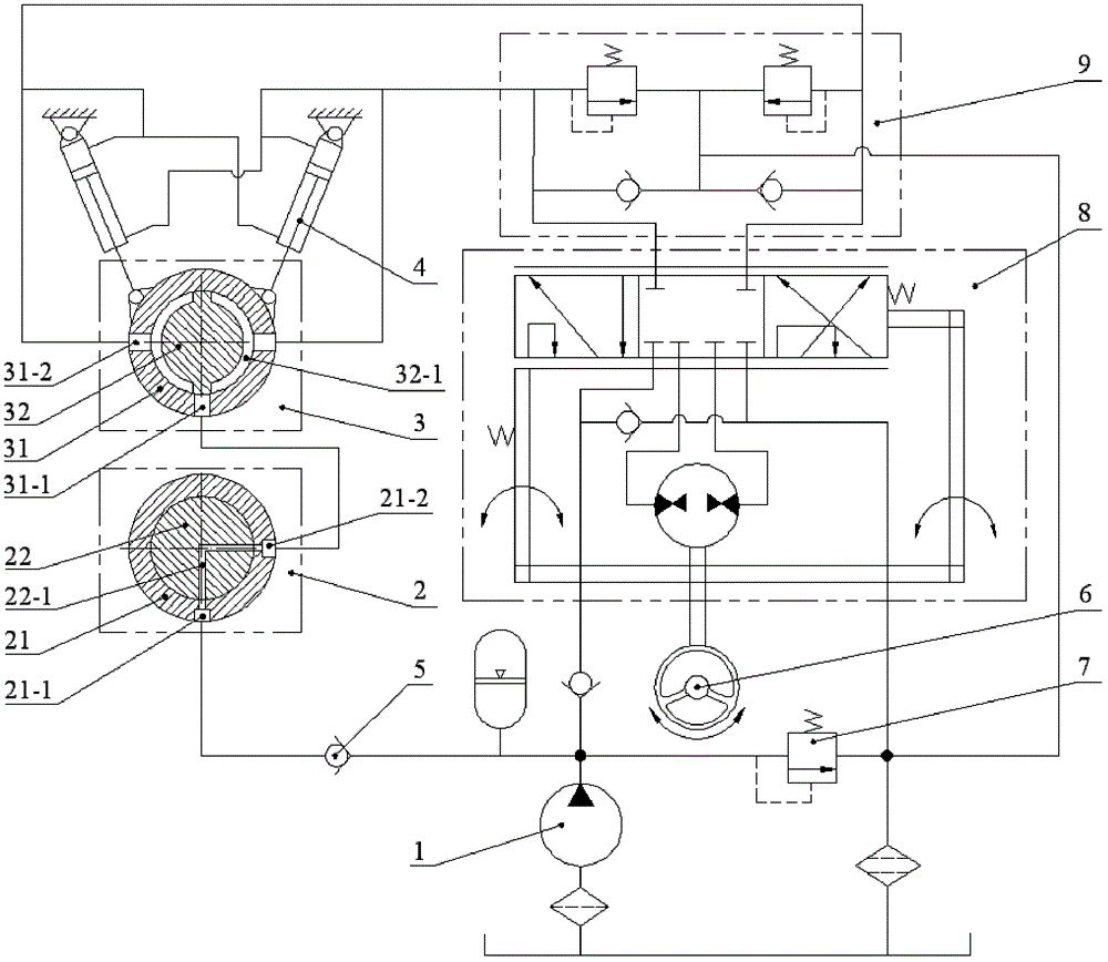
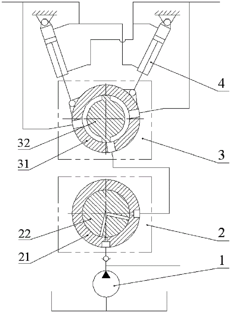
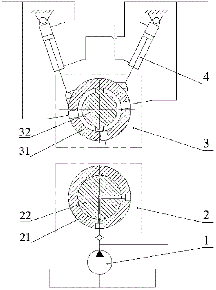
[0027] figure 1 As shown, the steering wheel angle positioning control device of the full hydraulic steering system of the present invention includes a hydraulic steering system, a steering cylinder 4 , an oil pump 1 , and a steering wheel 6 connected thereto. The device also includes a directional rotary valve 2 and a follow-up rotary valve 3; the directional rotary valve 2 is an open three-position two-way rotary valve, including a valve body 21 and a valve core 22, and the outer wall of the valve body 21 is provided with An oil inlet 21-1 and an oil outlet 21-2, the valve core 22 is provided with an oil passage 22-1, and the oil passage 22-1 is used to connect the oil inlet 21-1 and the oil outlet 21-2 The connection or closure between;

[0028] The follow-up rotary valve 3 is a closed three-position t...


PUM


Abstract

The invention discloses a turn angle positioning control device for a steering wheel of a full-hydraulic steering system. The turn angle positioning control device comprises a direction rotary valve and a follow-up rotary valve; the direction rotary valve comprises a valve body and a valve spool, an oil inlet and an oil outlet are formed in the outer wall of the valve body, an oil passage is arranged on the valve spool, and the oil inlet and the oil outlet can be communicated with each other or can stop being communicated with each other by the aid of the oil passage; the follow-up rotary valve comprises a valve body and a valve spool, an oil inlet and two oil outlets are formed in the outer wall of the valve body, the two oil outlets are symmetrically arranged, and two oil grooves which are not communicated with each other are formed in the circumference of the valve spool; when the valve spool of the follow-up rotary valve is located at a middle position, the oil inlet of the valve body of the follow-up rotary valve is sealed by the valve spool of the follow-up rotary valve, and when the valve spool is not located in the middle position, the oil inlet of the valve body of the follow-up rotary valve is communicated with one of the oil grooves and one of the oil outlets of the valve body of the follow-up rotary valve. The turn angle positioning control device has the advantages that the turn angle positioning control device only realizes an adjusting effect when the steering wheel turns or when the steering wheel is located in a middle position or when a turn angle of the steering wheel and turn angles of wheels are not aligned, accordingly, the turn angle positioning control device is excellent in reliability, and the performance of the original full-hydraulic steering system is unaffected; as the steering wheel keeps aligned constantly, misoperation of a driver can be reduced, and accidents are reduced.

Description

technical field [0001] The invention relates to the field of engineering vehicles, in particular to a steering wheel angle positioning control device for a full hydraulic steering system. Background technique [0002] Hydraulic steering systems are widely used in various engineering vehicles, such as loaders, forklifts, graders, large mining trucks, etc. Such engineering vehicles have high steering resistance, and the steering actuator is far away from the cab, so it is difficult to use a mechanically connected steering device. Using the hydraulic steering system, the steering power can be transmitted through the hydraulic pipeline for a long distance to realize the steering, the operation force is small, and the installation is convenient. Such as Figure 4 As shown, it is the simplest hydraulic steering system, and its composition includes: coarse filter 1, oil pump 2, steering cylinder 3, overload oil supplement group valve 4, steering gear 5, steering wheel 6, safety val...

Claims


Application Information

Patent Timeline
Patent Type & Authority Patents(China)
IPC IPC(8): B62D5/06B62D15/02
Inventor 迟永滨
Owner SOUTH CHINA UNIV OF TECH
Learn More