Floating wind turbine unit and offshore floating wind power plant

A wind turbine, floating technology, applied in the direction of wind motor combination, wind power generation, wind engine at right angles to the wind direction, etc., can solve the problems of large space occupation, difficulty, power amplification, etc., to achieve large wind output capacity and output wide range of effects

Inactive Publication Date: 2013-10-30
陈晓通
View PDF0 Cites 6 Cited by
  • Summary
  • Abstract
  • Description
  • Claims
  • Application Information

AI Technical Summary

Problems solved by technology

Because the greater the power of the fan, the blades will be greatly extended, which will force the tower to be heightened, resulting in an increase in the wind thrust on the top of the fan in the horizontal direction, thus forming a lever-type prying force. It will make the floating foundation easy to damage, and it is more likely to cause the overall nature of the inclined collapse
[0005] In addition, the generator equipment of the current wind turbine is all installed on the top, forming a top-heavy overall weight distribution pattern. Under the condition of floating foundation, the top weight of the wind turbine slightly deviates from the vertical center, which will form a lever-type super-amplified tilting collapse force, resulting in its Difficulty forming a stable setup on a single floating basis
[0006] It is the only way to solve the above problems by using multi-machine fixed connections to form a large-area rigid floating foundation. However, the yaw rotation of the current large-scale

Method used


Image

  • Floating wind turbine unit and offshore floating wind power plant
  • Floating wind turbine unit and offshore floating wind power plant
  • Floating wind turbine unit and offshore floating wind power plant

Examples


Embodiment Construction

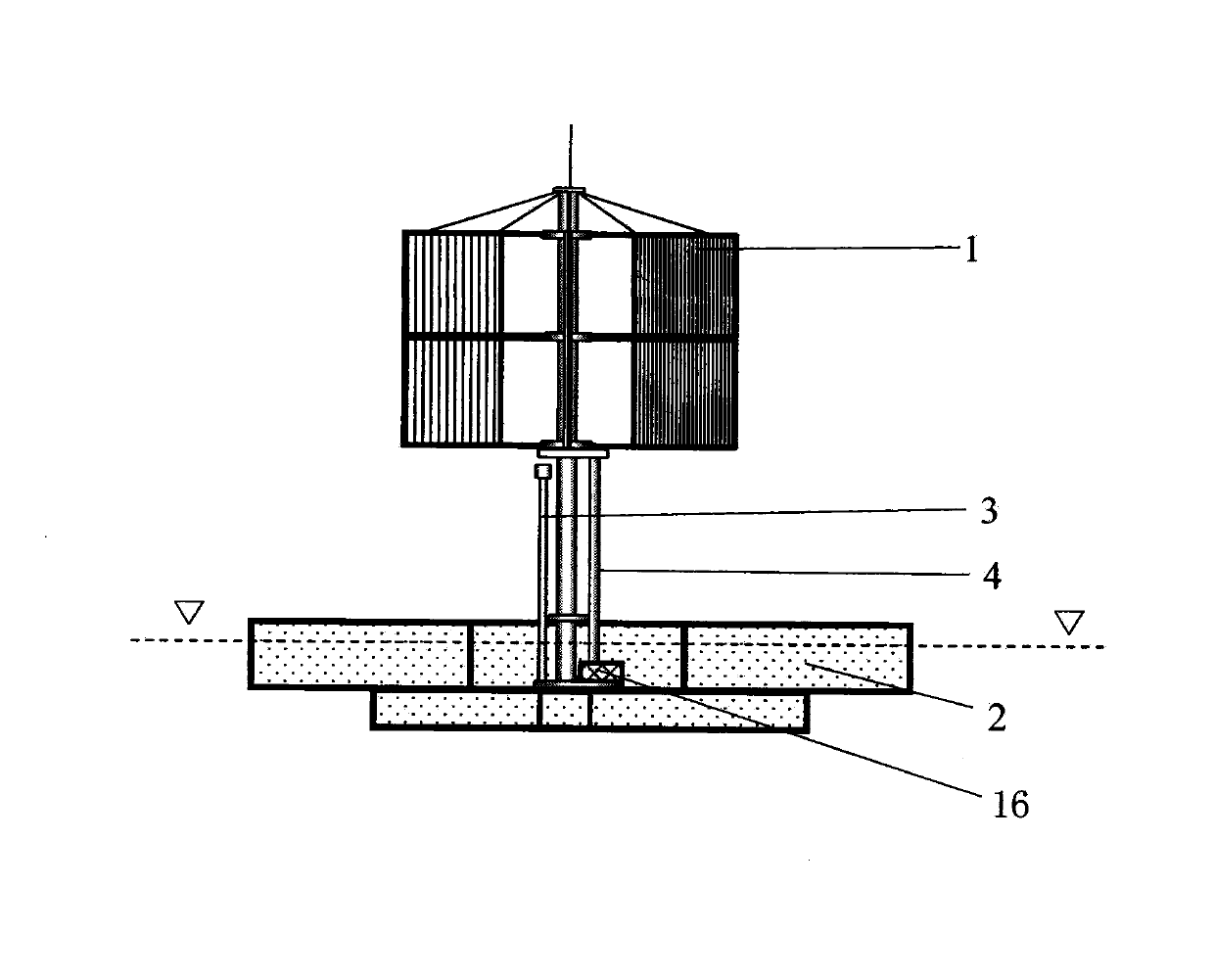
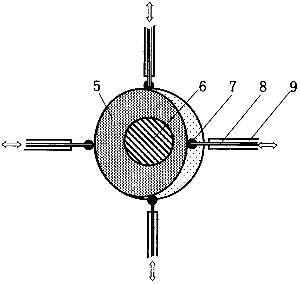
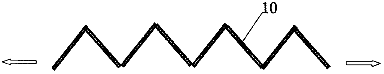
[0030] figure 1 It can be seen that the floating wind turbine is composed of a large vertical axis wind turbine 1 and a floating foundation 2, which forms an advantageous effect suitable for the overall structure and output mode of the floating wind turbine. The determination of the opening and closing direction of the arrayed blades 10 is carried out by wind driving the arrayed blades on the side facing the wind to realize the rotation of the wind wheel, and the opening and closing range of the arrayed blades is realized by adjusting the position of the push-pull rod 8 to achieve adjustment to adapt to changes in wind intensity Realize dual value regulation by adjusting and controlling the opening degree of the arranged blades and adjusting and controlling the multi-generator control system 16 to increase and reduce the number of generators put into work.

[0031] Because the weight of the upper part of the large-scale vertical axis wind turbine 1 is ultra-light compared with...


PUM


Abstract

A floating wind turbine unit is formed by a large-scale vertical-shaft wind turbine unit and a floating base which are closely fitted integrally. The upper box wall and lower box wall of the floating base are fixed with a tower of the large-scale vertical-shaft wind turbine unit. Rotating force output of the large-scale vertical-shaft wind turbine unit is transmitted through a driven gear unit and upper and lower driven shafts in a matching driven manner to a power generator or multiple generator adjusting system arranged in the floating base, so that stable wind power generation which is achieved by double valued adjustment and which is capable of matching with wind wheel force output capacity adjustment. An offshore floating wind power plant is formed by an integrated entire structure composed of more than two floating wind turbines in combination in multiple various forms. According to the floating wind turbine and the offshore floating wind power plant, key technical gaps of wind power developing complete machines of near offshore and far offshore can be filled, and gaps of large equipment of offshore wind power developing field can be filled.

Description

technical field [0001] The invention relates to a floating wind turbine and an offshore floating wind power station, which can fill in the gap in the key technology of offshore and remote sea wind energy development complete machines. Background technique [0002] Offshore wind power is strong and stable, especially in areas far away from the coast; offshore wind power can be built in a wide range of areas in the far sea, and there is extremely huge space and potential for wind power development. In addition, the coastal areas of most countries in the world are economically developed areas, and the demand for electricity is strong all year round. [0003] However, it is not easy to develop offshore wind power in the form of the existing large-scale horizontal-axis wind turbines, and it is even more impossible to develop wind energy in far-sea and deep-sea areas with it. Floating offshore wind turbines will be the most ideal and convenient , The cheapest option is the develo...

Claims


Application Information

Patent Timeline
IPC IPC(8): F03D9/00F03D3/00F03D7/06B63B35/00
CPCY02E10/74Y02E10/727
Inventor 陈晓通
Owner 陈晓通
Why Eureka
Try Eureka