Filter device, manufacturing method for filter device, and duplexer

A filter and elastic wave resonator technology, applied in the direction of electrical components, impedance networks, etc., can solve problems such as the difficulty of miniaturization of components

Inactive Publication Date: 2013-10-30
TAIYO YUDEN KK
View PDF7 Cites 28 Cited by
  • Summary
  • Abstract
  • Description
  • Claims
  • Application Information

AI Technical Summary

Problems solved by technology

[0007] However, the method of forming grooves between the transmitting and receiving filters and the method of enlarging the gap between the transmitting and receiving filters will increase the size of the board, so it is difficult to realize the miniaturization of components

Method used


Image

  • Filter device, manufacturing method for filter device, and duplexer
  • Filter device, manufacturing method for filter device, and duplexer
  • Filter device, manufacturing method for filter device, and duplexer

Examples


no. 1 Embodiment approach

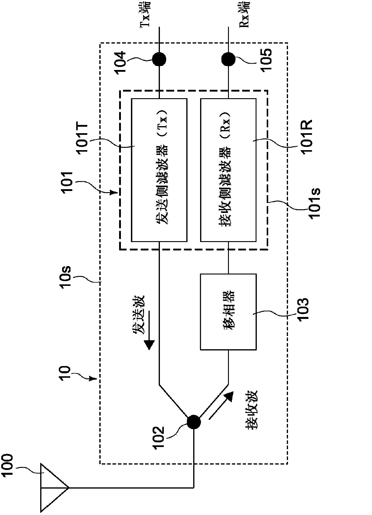
[0090] figure 1 It is a block diagram showing the configuration of a duplexer according to an embodiment of the present invention. First, the structure of the duplexer will be described.

[0091] [Diplexer]

[0092] The duplexer 10 of the present embodiment is a device for distributing transmission and reception signals mounted in mobile communication devices such as mobile phones. The duplexer 10 is used in a frequency division (FDD: Frequency Division Duplex) communication system such as UMTS (Universal Mobile Telecommunications System) and CDMA (Code Division Multiple Access), for example.

[0093] The duplexer 10 has a role of distributing transmission and reception signals so that one antenna can also be used for transmission and reception. The properties required for this are as follows.

[0094] (1) There is little leakage of the transmission signal to the reception frequency band or leakage of the reception signal to the transmission frequency band.

[0095] (2) T...

no. 2 Embodiment approach

[0185] Figure 7 It is a schematic cross-sectional view showing the configuration of the transmit-receive filter according to the second embodiment of the present invention. Hereinafter, configurations that are different from those of the first embodiment will be mainly described, and configurations that are the same as those in the above-mentioned embodiment will be given the same reference numerals and their descriptions will be omitted or simplified.

[0186] The transmission / reception filter 201 of this embodiment has a transmission filter 201T, a reception filter 201R, and a support substrate 201s. The transmission filter 201T has an FBAR as the first resonator ER21, and is formed in the first region R1 on the support substrate 201s. The reception filter 201R has a Lamb wave device as a second resonator ER22, and is formed in a second region R2 on the support substrate 201s.

[0187] The first resonator ER21 has a lower electrode layer 231 (first electrode layer), an up...

no. 3 Embodiment approach

[0207] Figure 9 It is a schematic cross-sectional view showing the structure of the transmit-receive filter according to the third embodiment of the present invention. Hereinafter, configurations that are different from those of the first embodiment will be mainly described, and configurations that are the same as those in the above-mentioned embodiment will be given the same reference numerals and their descriptions will be omitted or simplified.

[0208] The transmission / reception filter 301 of this embodiment has a transmission filter 301T, a reception filter 301R, and a support substrate 301s. The transmission filter 301T has an SMR as the first resonator ER31, and is formed in the first region R1 on the support substrate 301s. The reception filter 301R has a Lamb wave device as the second resonator ER32, and is formed in the second region R2 on the support substrate 301s.

[0209] The first resonator ER31 has a lower electrode layer 331 (first electrode layer), an uppe...


PUM


Abstract

A transmitting / receiving filter (filter device) according to one embodiment of the present invention is provided with a transmitting filter, a receiving filter, and a support substrate. The transmitting filter includes a first resonator constituted of a BAW device (FBAR, SMR). The receiving filter includes a second resonator constituted of a Lamb wave device. The support substrate supports both the transmitting filter and the receiving filter. The transmitting filter and the receiving filter are constituted of elastic wave resonators that resonate at different oscillation modes from each other, which allows miniaturization of the support substrate to be realized while preventing oscillation interference between the two filters.

Description

technical field [0001] The present invention relates to a filter device mounted in a mobile communication device such as a mobile phone, a method of manufacturing the filter device, and a duplexer. Background technique [0002] In recent years, in mobile communication equipment, for the purpose of increasing the speed of information transmission, miniaturization of duplexers, higher frequency of transmission and reception, and wider bandwidth are expected. The duplexer mentioned here is an element that has the following functions: In a communication system based on a frequency division method, in order to use one antenna to share transmission and reception, the transmitted and received signals are branched. Multiple filters with different operating frequencies on one side. Typically, the transmission filter and the reception filter use a surface acoustic wave (SAW: Surface Acoustic Wave) filter having a large electromechanical coupling coefficient and a small propagation lo...

Claims


Application Information

Patent Timeline
Patent Type & Authority Applications(China)
IPC IPC(8): H03H9/05H03H9/72H03H3/02
CPCH03H9/725H03H9/54H03H9/706H03H9/0576H03H9/0571H03H9/02228
Inventor 恩田阳介入枝泰成高桥智之笹岛裕一
Owner TAIYO YUDEN KK
Why Eureka
Try Eureka