Light receiver, light reception method and transmission system

A technology of light-receiving device and light-receiving part, which is applied to parts of TV systems, picture signal generators, TVs, etc., can solve the problems of large time difference and inability to shoot accurately, and achieve the effect of reducing time difference

Inactive Publication Date: 2013-10-30
KK TOSHIBA
View PDF6 Cites 10 Cited by
  • Summary
  • Abstract
  • Description
  • Claims
  • Application Information

AI Technical Summary

Problems solved by technology

In this case, when the time difference between the first shooting timing and the second shooting timing is large, accurate shooting may not be possible due to movement of the subject, etc.

Method used


Image

  • Light receiver, light reception method and transmission system
  • Light receiver, light reception method and transmission system
  • Light receiver, light reception method and transmission system

Examples


no. 1 Embodiment approach )

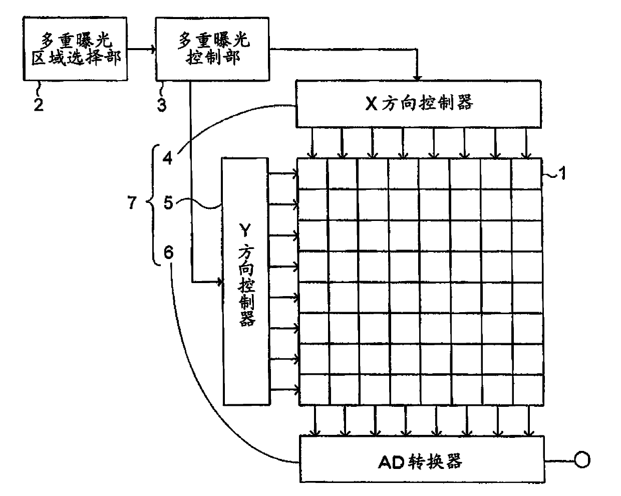
[0029] figure 1 It is a block diagram showing a schematic configuration of the light receiving device according to the first embodiment. The light receiving device includes a light receiving unit 1 , a multiple exposure area selection unit 2 , a multiple exposure control unit 3 , an X direction controller 4 , a Y direction controller 5 , and an AD (Analog to Digital) converter 6 .

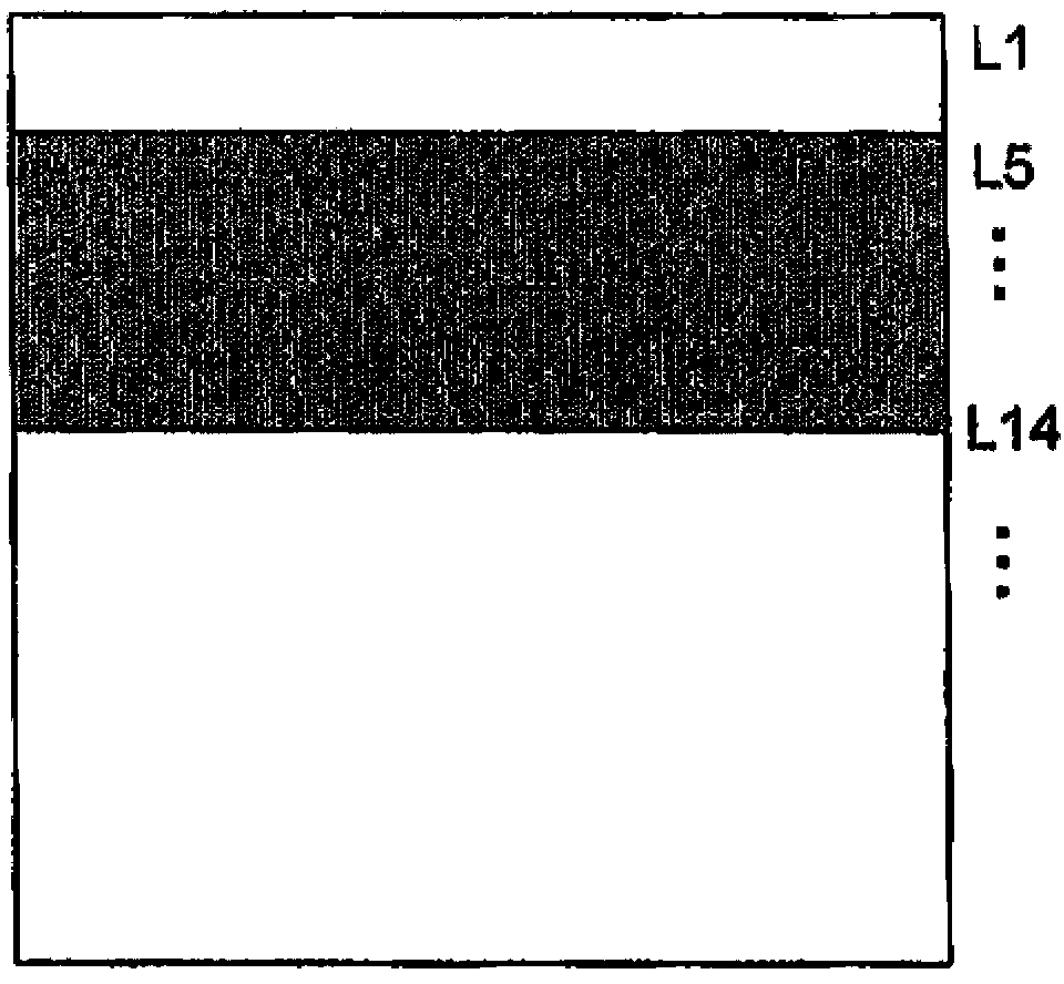
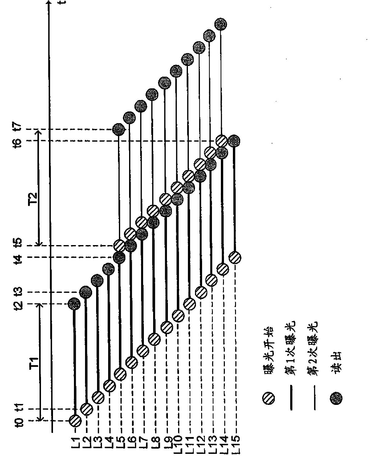
[0030] The light receiving unit 1 is a CMOS (Complimentary Metal Oxide Semiconductor) sensor, a CCD (Charge Coupled Device) sensor, or the like, and has a plurality of light receiving elements arranged in a matrix. More specifically, M light-receiving elements are arranged in the X (column) direction, and N light-receiving elements are arranged in the Y (row) direction. In other words, the light receiving unit 1 has N lines each including M light receiving elements. In addition, a predetermined range in front of the light receiving unit 1 can be imaged by exposing each light receiving element.

...

no. 2 Embodiment approach )

[0053] In the first embodiment described above, the multiple exposure area selection unit 2 selects the single exposure line and the multiple exposure line based on the register setting from the outside. On the other hand, in the second embodiment described below, selection is made based on an image obtained as a result of exposure, and an image obtained from the exposure amount of a line subjected to one exposure and an image obtained from a line exposed multiple times are used. Image processing is performed on the image obtained at the exposure level.

[0054] Figure 5 It is a block diagram showing a schematic configuration of the light receiving device according to the second embodiment. The main difference from the first embodiment is that the light receiving device further includes a frame buffer 8 , an image processing unit 9 , and processing by the multiple exposure area selection unit 2 .

[0055] The frame buffer 8 uses the output of the AD converter to generate an...

no. 3 Embodiment approach )

[0065] The third embodiment is one of the specific examples of the second embodiment, and is an example in which face detection is performed and noise removal processing is performed.

[0066] Figure 7 It is a block diagram showing a schematic configuration of the light receiving device according to the third embodiment. The multiple exposure area selection unit 2 in the present embodiment is a face detection unit 2 a that detects a human face from an image for multiple exposure area selection. Face detection is performed using a known method, such as detecting a face based on features such as skin color, eyes, nose, and mouth. In addition, the image processing unit 9 in the present embodiment is a noise removal unit 9 a that performs noise removal processing using the entire image and partial images.

[0067] Figure 8 is description Figure 7 The diagram of the processing operation of the light receiving device.

[0068] Figure 8 (a) is an example of an image for mul...


PUM


Abstract

According to one embodiment, a light receiver includes a light reception module, a multi-exposure area selector, a multi-exposure controller, and a readout module. The light reception module includes N lines, each of the N lines having a plurality of light receiving elements. The multi-exposure area selector is configured to select one or a plurality of single-exposure lines and one or a plurality of multi-exposure lines. The multi-exposure controller is configured to, per the unit time, perform an exposure on the single-exposure lines one time for a first exposure time; and a first exposure and a second exposure on the multi-exposure lines. The readout module is configured to read exposure amounts of the lines line by line. The multi-exposure controller is configured to start the second exposure on the multi-exposure lines before reading of the exposure amounts of all the single-exposure lines is completed.

Description

technical field [0001] The invention relates to a light receiving device, a light receiving method and a transmission system. Background technique [0002] A general light-receiving device shoots an object to be photographed once per unit time. However, depending on the purpose, only a specific area may be photographed multiple times. In this case, when the time difference between the first shooting timing and the second shooting timing is large, accurate shooting may not be possible due to movement of the subject or the like. Contents of the invention [0003] The problem to be solved by the present invention is to provide a light receiving device, a light receiving method, and a transmission system capable of reducing the time difference in shooting timing when multiple shootings are performed. [0004] The light receiving device of the embodiment is characterized in that it includes: a light receiving unit having N lines each including a plurality of light receiving e...

Claims


Application Information

Patent Timeline
Patent Type & Authority Applications(China)
IPC IPC(8): H04N5/235H04N9/04
CPCH04N5/2353H04N23/611H04N23/73H04N25/40
Inventor 立泽之康桧田和浩芦谷达治出口淳间岛秀明盛崎元博
Owner KK TOSHIBA
Why Eureka
Try Eureka