Electrode foils, current collectors, electrodes, and storage devices using these

A technology for current collectors and capacitor components, applied in the field of electrode foils, can solve the problems of tight electrical conductivity, insufficient chemical stability, difficult charging and discharging, and increased contact resistance, etc., to improve electrical conductivity and chemical stability. , good antioxidant effect

Active Publication Date: 2017-08-11
JAPAN CAPACITOR IND CO LTD
View PDF11 Cites 0 Cited by
  • Summary
  • Abstract
  • Description
  • Claims
  • Application Information

AI Technical Summary

Problems solved by technology

[0021] However, when the carbon layer is directly formed on the metal foil, the contact resistance between the current collector and the electrode layer gradually increases due to the lack of adhesion between the metal foil and the carbon coating layer, electrical conductivity, and chemical stability. Shortly there will be a decrease in output density or an increase in internal resistance, making it difficult to perform rapid charge and discharge
In addition, according to the investigation of the present inventors, there are patent documents 8 to 11 in the relevant prior art documents, but these disclosed coating structures also have the same problem

Method used


Image

  • Electrode foils, current collectors, electrodes, and storage devices using these
  • Electrode foils, current collectors, electrodes, and storage devices using these
  • Electrode foils, current collectors, electrodes, and storage devices using these

Examples


no. 1 Embodiment approach

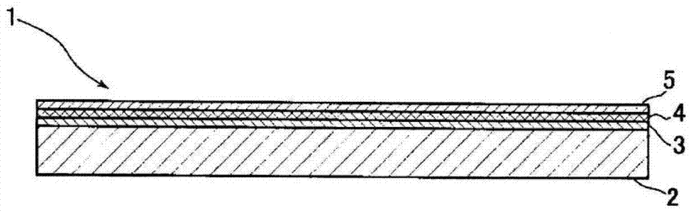
[0101] The following description: On the non-roughened aluminum foil, a first conductive layer composed of Ti or Al, a mixed layer composed of Ti or Al and carbon, and a second conductive layer composed of carbon are formed. Layered cathode foil, and a solid electrolytic capacitor fabricated using the cathode foil, are an embodiment of the present invention. However, as already explained, the aluminum foil used as the substrate and the Ti or Al used to form the first conductive layer can be replaced by other materials, or as explained by the performance test data, even if the surface of the substrate is not roughened Therefore, the cathode foil of the present invention also has good characteristics.

[0102] (cathode foil of the present invention)

[0103] figure 1 It is a cross-sectional view showing the layer structure of the cathode foil 1 according to the above-mentioned one embodiment. The cathode foil 1 is: a smooth aluminum foil 2 that has not been roughened by etchi...

Embodiment 1

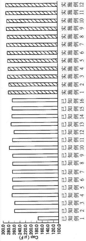
[0159] The smooth aluminum foil was etched to form a cathode foil having a Ti coating of 0.2 μm, a Ti and carbon mixed layer a of 0.1 μm, and a carbon coating of 0.2 μm.

Embodiment 2

[0161] The smooth aluminum foil was etched to form a cathode foil having a Ti coating of 0.008 μm, a Ti and carbon mixed layer a of 0.004 μm, and a carbon coating of 0.008 μm.


PUM

PropertyMeasurementUnit
thicknessaaaaaaaaaa
thicknessaaaaaaaaaa

Abstract

The subject of the present invention is to achieve an increase in electrostatic capacitance, a reduction in ESR and leakage current, an improvement in heat resistance, and a reduction in manufacturing cost in the cathode foil for solid electrolytic capacitors, and to improve the performance of storage batteries, electric double layer capacitors, hybrid The output density of power storage components such as capacitors can be improved, and the life characteristics can be improved by realizing rapid charge and discharge. The solution of the present invention is to use the following cathode foil or current collector. The cathode foil or current collector is a mixed layer formed by forming a metal layer on a metal foil and a substance constituting the metal layer and carbon, and a carbon layer substantially composed of carbon; the composition of the mixed layer is such that, from the metal layer toward the carbon layer, the composition substantially contains only the substance constituting the metal layer changes to the composition substantially containing only carbon.

Description

technical field [0001] The present invention relates to a solid electrolytic capacitor having a solid electrolyte layer (typically a conductive polymer layer) formed therein, and an electrode foil usable in such a capacitor. In addition, the present invention relates to a current collector, an electrode, and an electrical storage component such as a storage battery, an electric double-layer capacitor, or a hybrid capacitor using these. Background technique [0002] Prior Art Related to Solid Electrolytic Capacitors [0003] In recent years, as the operating frequency of electronic equipment has become higher, electrolytic capacitors, one of electronic components, have been required to have excellent impedance characteristics in a region of higher operating frequency than before. In response to this demand, various solid electrolytic capacitors using conductive polymers with high electrical conductivity as solid electrolytes have been developed. This type of solid electroly...

Claims


Application Information

Patent Timeline
Patent Type & Authority Patents(China)
IPC IPC(8): H01G11/32H01G11/70H01M4/66H01M4/13
CPCH01G9/0425H01G9/15H01G11/06H01G11/28H01G11/34H01G11/36H01G11/50H01G11/70H01M4/661H01M4/663H01M4/666H01M4/667H01M10/0525Y02E60/10Y02E60/13Y10T428/24355Y10T428/31678H01G9/04H01G9/042H01G9/055H01G11/30H01G11/32
Inventor 吉村光男吉冈功二
Owner JAPAN CAPACITOR IND CO LTD
Why Eureka
Try Eureka