Continuous die using flanging knife flanging and sheet metal flanging processing method

A processing method and technology of sheet metal parts, applied in the field of flanging processing of sheet metal parts, can solve problems such as insufficient product quality, long processing process, and bulky volume, and achieve simplified structure and use methods, high product quality, and technological process simplified effect

Active Publication Date: 2016-01-20
KUNSHAN DAYA AUTO PARTS
View PDF7 Cites 0 Cited by
  • Summary
  • Abstract
  • Description
  • Claims
  • Application Information

AI Technical Summary

Problems solved by technology

[0004] The flanging mechanism with inclined wedge includes many components including the downward inclined wedge 41 and the horizontal inclined wedge 42. The structure is complex, the volume is huge, the processing process is long, and the quality of the processed product is not good enough

Method used


Image

  • Continuous die using flanging knife flanging and sheet metal flanging processing method
  • Continuous die using flanging knife flanging and sheet metal flanging processing method

Examples


Embodiment 1

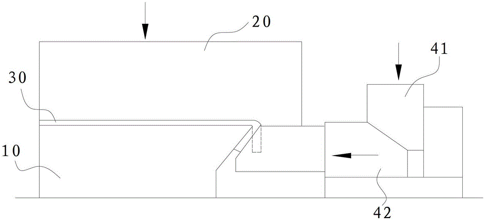
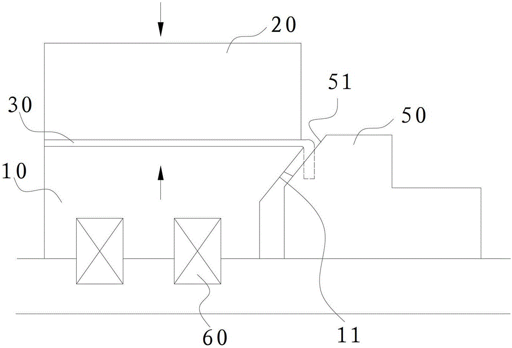
[0031] Such as figure 2 As shown, the preferred embodiment provides a continuous mold using a flanging knife to flanging, the continuous mold is provided with a flanging station, the flanging station is provided with a lower mold 10 and a mold that is compatible with the lower mold 10 The upper die 20, the flanging knife 50 fixedly arranged beside the lower die 10, and the spring arranged under the lower die 10.

[0032] The flanging station is divided into two sub-stations, and a flanging knife 50 is set on each sub-station. The angle of the processing surface 51 on the first divisional station flanging knife 50 is 60 ° (60 ° angle with the preformed shape), and the processing surface 51 angle on the second divisional position flanging knife 50 is 0 ° (with the preformed shape). parallel to the shape).

[0033] Correspondingly, the angle of the lower mold processing surface 11 of the first sub-station is 60°, and the angle of the lower mold processing surface 11 of the sec...

Embodiment 2

[0041] This preferred embodiment provides a continuous mold for flanging using a flanging knife, the basic structure of which is the same as that of the first preferred embodiment.

[0042] The difference is that: when the upper mold is lifted, the lifting of the lower mold is not limited to the spring, and any reset device that can realize the reset function can be used. The number of sub-stations included in the flanging process is not limited to two, and is determined according to the specific shape and processing conditions of the workpiece. Correspondingly, the angle of the processing surface of the flanging knife used in each sub-station increases sequentially to finally meet the set flanging angle requirements.

[0043] The processing flow of this preferred embodiment is also the same as that of the first substrate of the preferred embodiment. The difference is that decomposing the flanging process into multiple steps or one-step flanging depends on the specific produc...


PUM


Abstract

The invention discloses a progressive die flanged by a flanging knife and a metal sheet flanging processing method and aims to solve the problems of complex structure and large volume of an existing device. A flanging station is formed on the progressive die flanged by the flanging knife; a lower die, an upper die and the flanging knife are arranged on the flanging station; and an angle of a processing surface of the flanging knife is fitted with the shape of a workpiece. According to the metal sheet flanging processing method, a flanging part of the workpiece is fixed by the flanging knife and the lower die and then is flanged under the action of the pressure of the upper die. According to the progressive die flanged by the flanging knife, the structure and the using method are simplified, and the occupied area is reduced. According to the metal sheet flanging processing method, the flanging effect is better, the quality of a product is higher, and the technical flow is simplified. Furthermore, the efficiency is improved, the cost is reduced, and the metal sheet flanging processing method is suitable for the flanging technologies for various metal sheets.

Description

technical field [0001] The invention relates to a continuous mold using a flanging knife and a method for flanging a sheet metal part using the continuous mold. Background technique [0002] The production and processing of sheet metal parts usually includes drawing, cutting and flanging processes. When the above processes are carried out separately, more manpower is required to perform handling, loading, proofreading, etc., resulting in low production efficiency and poor processing quality. The continuous die integrates multiple processes in sheet metal processing, and semi-finished or finished products can be obtained after one feeding, which improves work efficiency and safety. [0003] The existing continuous die flanging process tool is to utilize the oblique wedge assembly to carry out flanging. Such as figure 1 As shown, a workpiece 30 is placed between the lower die 10 and the upper die 20 . The end (flange portion) of the workpiece 30 is pre-bent, as shown by the...

Claims


Application Information

Patent Timeline
Patent Type & Authority Patents(China)
IPC IPC(8): B21D37/10B21D19/00
Inventor 赵国文
Owner KUNSHAN DAYA AUTO PARTS
Why Eureka
Try Eureka