Progressive rotational shear feeding method and progressive rotational shearing machine

A rotary shearing, progressive technology, applied in the direction of shearing device, shearing machine equipment, accessories of shearing machine, etc., can solve problems such as deformation of blanks, slump of incisions, etc.

Active Publication Date: 2013-11-13
四川名钺机械设备制造有限公司
View PDF8 Cites 1 Cited by
  • Summary
  • Abstract
  • Description
  • Claims
  • Application Information

AI Technical Summary

Problems solved by technology

The disadvantages are: the incision has defects such as slope, rounded corners, and collapsed c

Method used


Image

  • Progressive rotational shear feeding method and progressive rotational shearing machine
  • Progressive rotational shear feeding method and progressive rotational shearing machine
  • Progressive rotational shear feeding method and progressive rotational shearing machine

Examples


Embodiment 1

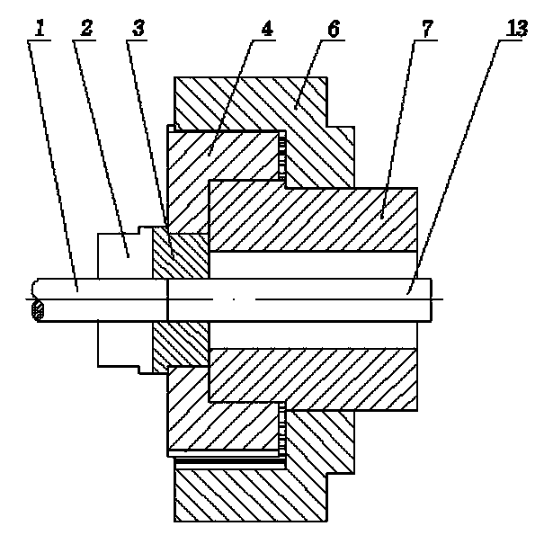
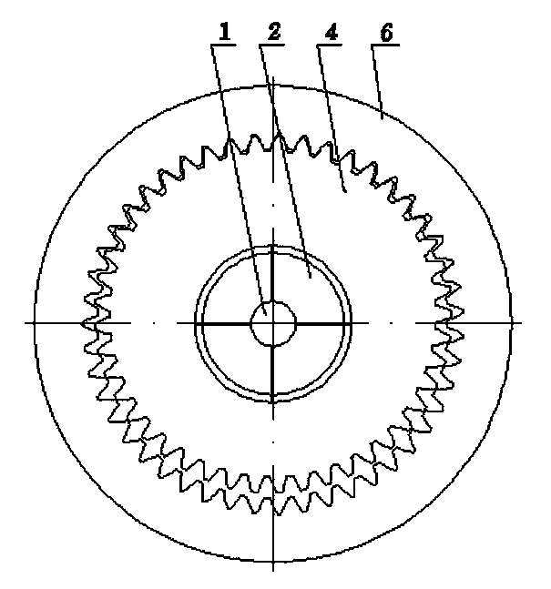
[0041] Such as figure 1 , 2 As shown, the double crankshaft mechanism includes the driving crankshaft, the active internal meshing ring gear sleeved on the concentric end of the driving crankshaft, the internal meshing external gear sleeved on the eccentric end of the driving crankshaft and meshed with the internal meshing ring gear; the movable knife is installed in the eccentric hole of the internal meshing external gear Inside.

[0042] The crankshaft rotates around the axis, and the internal meshing ring gear rotates around the axis. When there is a speed difference between the two rotation speeds, the moving knife performs a constant speed helical motion.

Embodiment 2

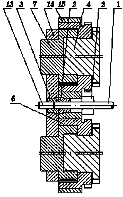
[0044] This embodiment is a modified structure of Embodiment 1, and the double crankshaft mechanism is set as two sets, and the moving knife plate structure is added. Such as image 3 , 4 shown. The double crankshaft mechanism includes two driving crankshafts, two internal meshing ring gears sleeved on the concentric end of the driving crankshaft, two internal meshing external gears sleeved on the eccentric end of the driving crankshaft and meshed with the internal meshing ring gear; two sets of driving crankshafts, driving internal meshing gears The ring and the inner meshing outer gear are symmetrical to the axis center of the moving knife; the moving knife plate is installed on the two inner meshing outer gears, and the moving knife is installed in the middle of the moving knife plate.

[0045] The two crankshafts rotate at the same speed, and the two internal meshing ring gears rotate at the same speed. When there is a speed difference between the two rotation speeds, th...

Embodiment 3

[0048] Such as Figure 5 , 6 As shown, the double crankshaft mechanism includes a driving crankshaft and an eccentric shaft sleeved on the driving crankshaft; the moving knife is installed in the shaft hole of the eccentric shaft.

[0049] The active crankshaft rotates around the axis, and the eccentric shaft rotates around the axis. When there is a speed difference between the two rotation speeds, the moving knife performs a constant-speed spiral motion.


PUM


Abstract

The invention discloses a progressive rotational shear feeding method and a progressive rotational shearing machine. The progressive rotational shearing machine comprises a clamping stationary knife for fixing a blank and a moving knife for shearing a feed section of the blank, and is characterized in that the clamping force of the clamping stationary knife and the moving knife is radial, and two or more than two stressed parts are availableand centrosymmetric; and the moving knife is sleeved in a dual-crankshaft mechanism or a flywheel slider mechanism, the dual-crankshaft mechanism or the flywheel slider mechanism drives the moving knife to rotate the feed section of the blank by 360 degrees and progressively shear the feed section along the radial direction. The progressive rotational shear feeding method solves the problems of the conventional cutting feeding method and shear feeding method; and the invention has the advantages that the efficiency is high, the waste of raw materials is avoided, the cost is low, the cut is flat without bevel angles or collapsed corners, the blank is not deformed, the blank with the extremely small draw ratio can be cut off, pipes and sections can be cut off and the like.

Description

technical field [0001] The invention belongs to the field of metal material shearing and blanking equipment. Background technique [0002] Existing metal material blanking methods include cutting blanking and shearing blanking. [0003] Cutting and blanking The incision is smooth, the blank has no deformation, and the material with any length-to-diameter ratio can be cut. The disadvantage is waste of raw materials, low efficiency and high cost. [0004] High cutting efficiency, no waste of raw materials, low cost. The disadvantages are; the incision has defects such as slope, rounded corners, and collapsed corners, and the blank is deformed, and the material with an aspect ratio of 1 can be cut at most. It is difficult to cut pipes and profiles. Contents of the invention [0005] The purpose of the present invention is to provide a blank with high efficiency, no waste of raw materials, low cost, flat cut without bevel or slump, no deformation of the blank, capable of c...

Claims


Application Information

Patent Timeline
IPC IPC(8): B23D19/00B23D33/00
Inventor 罗建国
Owner 四川名钺机械设备制造有限公司
Why Eureka
Try Eureka