
Subsection millisecond differential blasting method in blasthole

A technology of differential blasting and blasting holes, which is applied in blasting and other directions, can solve the problems of slowing down the progress of the project and increasing the cost of blasting, and achieve the effects of reducing blasting vibration, improving blasting effect, and reducing the cost of explosives

Inactive Publication Date: 2013-11-13
GUIZHOU XINLIAN BLAST ENG GRP
View PDF5 Cites 11 Cited by
  • Summary
  • Abstract
  • Description
  • Claims
  • Application Information

AI Technical Summary

Problems solved by technology

Therefore, when using hole-by-hole differential blasting, when the differential interval time reaches a certain value and the blasting seismic waves are completely staggered, the damping effect of differential blasting will reach the limit. At this time, to further reduce the blasting vibration, it is necessary to increase the number of drilling holes. Reducing the single-hole charge will inevitably slow down the project progress and increase the blasting cost. At this time, if the blasting vibration needs to be further reduced, other methods need to be introduced

Method used


Image

  • Subsection millisecond differential blasting method in blasthole

Examples


Embodiment Construction

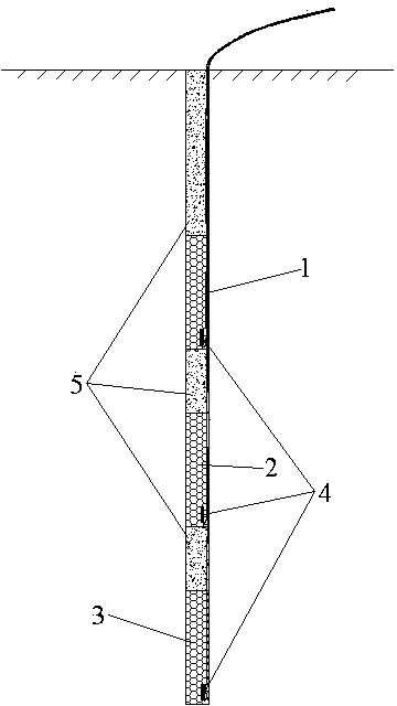
[0016] Such as figure 1 As shown, the blast hole has a diameter of 90mm and a hole depth of 10m, and the blasting parameters determined by the general continuous coupling charge design are the blockage length of 3m; it can be confirmed through the field test that when the segment distance is 0.8m, there will be no martyrdom phenomenon. Then the segment spacing can be determined as 1.0m.

[0017] Three-stage charge is used, which are respectively upper charge segment 1, middle charge segment 2, and lower charge segment 3. Each charge segment adopts the same length, then the upper charge segment 1, middle charge segment Section 2 and section 3 of the bottom charge are both 1.8m long, and the top charge section 1, the middle charge section 2, and the bottom charge section 3 are sequentially filled with conventional charge means, and the on-site Clay, fine sand, etc. are used as filler 5 to densely fill the on-site blockage; thus, the plugging length of the blast hole opening is ...


PUM


Abstract

The invention discloses a subsection millisecond differential blasting method in a blasthole, which mainly comprises the following operating steps of filling explosives in a sectioned manner by using a spaced loading method in the blasthole, wherein the length of each subsection of filled explosives is equal; in the explosive filling process, enabling the distance between every two adjacent subsections of explosives is greater than an induced detonation distance; determining continuous coupling explosive loading parameters according to an empirical formula of medium-length hole parameters and further determining specific parameters of divided charge in the blasthole; and densely filling a space between every two adjacent subsections of explosives by using materials such as clay and rock powder, wherein each subsection of explosives is detonated by using a detonator, all ways of initiation are reverse initiation, namely all detonators are arranged at the bottoms of the subsections filled with the explosives after being arranged in igniting explosive packages, the energy-gathering caves of the detonators face to apertures, the differential interval time of the subsections filled with the explosives is 15-40 milliseconds, and the initiation sequence of the subsections filled with the explosives is from top to bottom. According to the subsection millisecond differential blasting method in the blasthole, blast vibration can be further reduced on the basis of the millisecond blasting among blastholes and the blasting crushing effect can be effectively improved.

Description

technical field [0001] The invention relates to a segmental millisecond differential blasting method in a blast hole. Background technique [0002] Blasting vibration is the most important consideration in blasting design and construction to ensure blasting safety. Because rock drilling and blasting will inevitably produce vibration, it is impossible to completely eliminate the blasting vibration only by taking measures to reduce it. Vibration control means can be divided into two forms: active and passive. The active control means can only reduce the technical means of blasting vibration from the source, and the passive means is the technical means to weaken the seismic wave suffered by the protected object after the seismic wave is generated. In the long-term blasting practice, a variety of technical means to reduce blasting vibration, such as differential blasting and excavation of shock absorbing trenches, have emerged as the times require. Among them, differential blas...

Claims


Application Information

Patent Timeline
Patent Type & Authority Applications(China)
IPC IPC(8): F42D1/00
Inventor 康强赵明生池恩安胡浩川沈晓松魏兴谢春明明悦
Owner GUIZHOU XINLIAN BLAST ENG GRP
Learn More