Stamping die structure for circumferential bolts and longitudinal bolts for rail transit

A technology of circumferential bolts and longitudinal bolts, which is applied in the field of mechanical equipment, can solve the problems of increased workload, low production efficiency, and high production costs, and achieve the effects of reliable operation, long service life, and improved product quality and production efficiency

Active Publication Date: 2013-11-20
盐城诚创铸造有限公司
View PDF6 Cites 6 Cited by
  • Summary
  • Abstract
  • Description
  • Claims
  • Application Information

AI Technical Summary

Problems solved by technology

This method of repeated stamping processing has resulted in increased workload and low production efficiency, so the production cost is relatively high
In the prior art, there is also equipment that uses one-time stamping and forming, but the stamping dies are all designed with rollers. Because the contact surface between the rollers and the stamped product is too small, and the stamping ratio of the stamped circumferential bolts and longitudinal bolts is relatively large, so The surface of the stamped product often has obvious concave and convex defects, so the finish of the product is poor, resulting in an ugly appearance

Method used


Image

  • Stamping die structure for circumferential bolts and longitudinal bolts for rail transit
  • Stamping die structure for circumferential bolts and longitudinal bolts for rail transit
  • Stamping die structure for circumferential bolts and longitudinal bolts for rail transit

Examples


Embodiment Construction

[0023] Embodiments of the present invention will be described in further detail below in conjunction with the accompanying drawings.

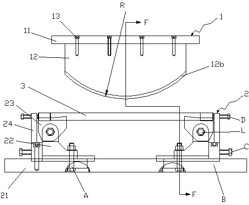
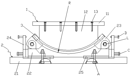
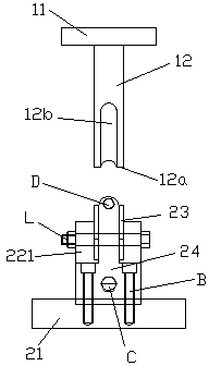
[0024] Figure 1 to Figure 6 Shown is the structural representation of the present invention.

[0025] The reference signs are: bracket fixing bolt A, backing fixing bolt B, bracket adjusting bolt C, upper adjusting bolt D, bracket pin shaft L, upper stamping die 1, upper stamping top plate 11, upper stamping template 12, stamping contact surface 12a, stamping upper groove arc 12b, upper die fixing screw 13, lower stamping die 2, stamping die bottom plate 21, strip-shaped sliding hole 21a, guide positioning groove 21b, backing positioning groove 21c, stamping movable block bracket 22, positioning hole 22a, guide chute 22b, support lug 221, stamping movable block 23, stamping support surface 23a, stamping lower groove arc 23b, backing adjustment plate 24, bracket positioning key 25, stamping product 3.

[0026] Such as Figure 1 to Figure 6 A...


PUM


Abstract

The invention discloses a stamping die structure for circumferential bolts and longitudinal bolts for rail transit. The stamping die structure comprises an upper stamping die and a lower stamping die which are arranged in an up-down manner. A stamping contact surface of the upper stamping die is an arc-shaped surface with the radius R, and an upper stamping groove arc which is matched with a peripheral arc of a stamped product is formed in the stamping contact surface along the integral arc length of the stamping contact surface; the lower stamping die comprises a stamping die bottom plate and two stamping movable block supports, the distance between the two stamping movable block supports is adjustable, the two stamping movable block supports are bilaterally arranged on the stamping die bottom plate, a stamping movable block is rotationally pivotally connected onto each stamping movable block support in a hole and shaft matching manner, a lower stamping groove arc which is correspondingly matched with the upper stamping groove arc is formed in a stamping supporting surface of each stamping movable block, and two ends of the stamped product are respectively supported in the lower stamping groove arcs of the two stamping movable blocks in an erected manner. The stamping die structure has the advantages that the upper stamping die and the lower stamping die move up and down and are matched with each other to squeeze the stamped product, so that a rod of the stamped product is forced to deform and is bent to form an arc with the radius R.

Description

technical field [0001] The invention relates to the technical field of mechanical equipment, in particular to die equipment for railway ring bolts and longitudinal bolts, in particular to stamping die structures for rail transit ring bolts and longitudinal bolts. Background technique [0002] Circumferential bolts and longitudinal bolts are a standard part used in rail transit. With the construction and promotion of rail transit networks in major and medium-sized cities across the country, the number of hoop bolts or longitudinal bolts has also increased sharply. But because the shank of this kind of bolt has an arc-shaped bend in space, it is not easy to ensure the quality of the product. The main difficulty lies in the process of punching or bending the product. Circumferential bolts and longitudinal bolts are both made of metal steel. Due to the rebound coefficient of metal steel, ordinary stamping dies usually cannot meet the design requirements of the drawings after the...

Claims


Application Information

Patent Timeline
Patent Type & Authority Applications(China)
IPC IPC(8): B21D37/10
Inventor 蔡体勇
Owner 盐城诚创铸造有限公司
Why Eureka
Try Eureka