Multi-head tube cutter

A pipe cutting machine, multi-head technology, applied in metal sawing equipment, sawing machine equipment, metal processing and other directions, can solve the problems of high failure rate, complex structure, high manufacturing and maintenance costs

Active Publication Date: 2013-11-20
HUIZHOU JIALONGDA SCI & TECH LTD
View PDF12 Cites 9 Cited by
  • Summary
  • Abstract
  • Description
  • Claims
  • Application Information

AI Technical Summary

Problems solved by technology

But its defects are also obvious: First, each cutting mechanism needs to be equipped with a motor, which is very costly, and as long as one of these motors fails or is damaged, the entire equipment must be shut down for maintenance, and the failure rate is very high; Secondly, when performing cutting work, it is necessary to push the entire cutting mechanism including the mot

Method used


Image

  • Multi-head tube cutter
  • Multi-head tube cutter
  • Multi-head tube cutter

Examples


Embodiment Construction

[0027] In order to make the technical problems, technical solutions and advantages to be solved by the present invention clearer, the present invention will be further described in detail below in conjunction with the accompanying drawings and embodiments. It should be understood that the specific embodiments described here are only used to explain the present invention, not to limit the present invention.

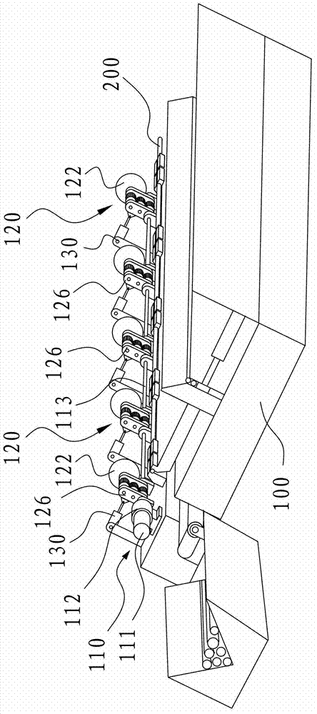
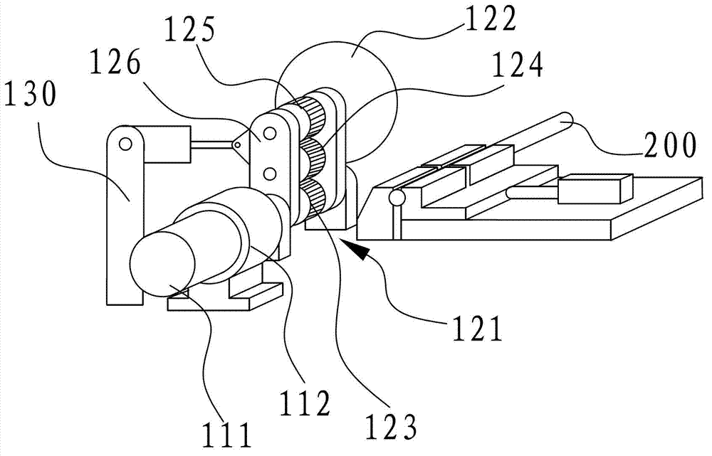
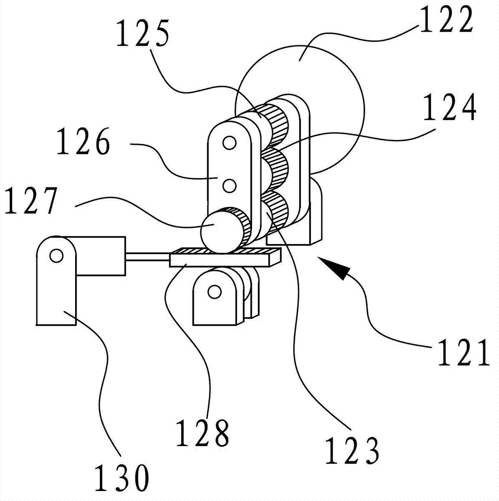
[0028] All the accompanying drawings only disclose the parts closely related to the present invention, rather than the entire structure of the pipe cutting machine. like Figure 1~4 The first embodiment of the invention shown is a multi-head pipe cutter. As shown in the figure, it includes a frame 100 , a power device 110 , a pushing device 130 and at least two sets of pipe cutting units 120 . The structure of the pipe cutting unit 120 can be the same, and the quantity can be determined according to actual needs, figure 1 5 sets are shown. Generally, multiple sets can ...


PUM


Abstract

The invention relates to the technical field of tubular material processing, in particular to a multi-head tube cutter with multiple tube cutting units simultaneously cutting tubular materials. The multi-head tube cutter comprises a frame, a power device and at least two sets of tube cutting units. The power device and the tube cutting units are all mounted on the frame. Each tube cutting unit comprises a transmission device and a cutting device mounted on the transmission device. The power device is connected with the transmission device of each tube cutting unit. Therefore, only one power device is needed to drive the transmission devices in all the tube cutting units, and accordingly the cutting devices are driven to cut to-be-processed tubes. Compared with the prior art, the multi-head tube cutter has the advantages that no matter how many sets of tube cutting units are provided, only one power device is needed, cost is reduced effectively, and the probability of fault occurrence is reduced greatly.

Description

technical field [0001] The invention relates to the technical field of processing tubular materials, in particular to a multi-head pipe cutting machine which has a plurality of pipe cutting units to simultaneously cut tubular materials. Background technique [0002] In the processing industry of pipes, especially metal pipes, it is often necessary to cut the pipes according to certain size requirements. This simple and repetitive work was completely done by manual cutting in the early days. Subsequently, equipment specially used for cutting pipes appeared on the market, that is, pipe cutting machines. [0003] This kind of pipe cutting machine mainly includes a frame on which a set of pipe cutting unit is installed, mainly including a motor, a worm gear and a saw blade. The processed pipe is sent to the saw blade for section-by-section cutting. Although this cutting machine has realized a certain degree of automation, it can only cut one section at a time. If a pipe needs...

Claims


Application Information

Patent Timeline
IPC IPC(8): B23D45/10B23D47/12B23D47/10B23D47/04
CPCB23D45/12B23D45/10B23D47/10B23D47/12B26D1/16B26D3/161B26D7/0625B26D7/0683
Inventor 唐敏
Owner HUIZHOU JIALONGDA SCI & TECH LTD
Why Eureka
Try Eureka