Assembly method and assembly system

A technology of flat tubes and sensors, which is applied in the field of assembly methods and systems, can solve the problems of large damage to parts and components, and achieve the effects of reducing enterprise expenses, reducing equipment maintenance and replacement costs, and reducing energy consumption

Inactive Publication Date: 2013-11-20
HUIZHOU DONGFENG YIJIN IND
View PDF11 Cites 0 Cited by
  • Summary
  • Abstract
  • Description
  • Claims
  • Application Information

AI Technical Summary

Problems solved by technology

[0004] Chinese invention patent specification CN101362216A discloses a blanking machine, the shrinkage blanking machine is composed of a feeding device and a cutting device, the feeding device includes a guide rail seat, a feeding cylinder is arranged on the guide rail seat, and the guide rail seat is fixed on the machine tool through the guide rail On the base, the guide rail seat and the guide rail can move relatively. The end of the feeding cylinder is provided with an inner pull tube lock nut, and the inner pull tube is fixed on the inner pull tube lock nut. The front end of the inner pull tube is provided with Spring collets, the piston column of the feeding cylinder is provided with connecting splines, the connecting splines are connected with an outer pusher tube, and the front end of the outer pusher tube is provided with an inner clamping sleeve. Manual feeding is replaced by mechanical feeding, which improves the feeding speed and accuracy. Because in the actual process, the parts of the blanking machine need to be repeatedly moved, and the blanking machine is not equipped with sensors and blanking control devices. There are problems of repeated use of devices, frequent maintenance and replacement, and problems of cutting control
[0005] In the actual assembly process, due to the repeated and frequent actions of the feeding device of the assembly system, the damage to the parts is relatively large, and continuous maintenance is required

Method used


Image

  • Assembly method and assembly system
  • Assembly method and assembly system
  • Assembly method and assembly system

Examples


Embodiment Construction

[0049] The technical solutions in the embodiments of the present invention will be clearly and completely described below in conjunction with the accompanying drawings in the embodiments of the present invention. Based on the embodiments of the present invention, all other embodiments obtained by persons of ordinary skill in the art without creative efforts fall within the protection scope of the present invention.

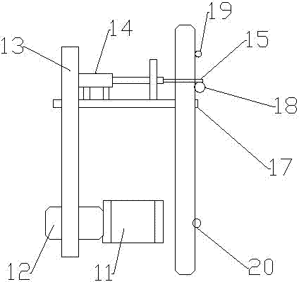
[0050] like figure 1 As shown in the assembly system of the present invention, the assembly system includes a blanking system 10, a blanking platform 17, a flat tube drag bar 15, and a flat tube sensor 18;

[0051] The blanking system 10 is mainly composed of a variable speed elevator 12, a servo motor 11, a flat tube dragging telescopic cylinder 14, a flat tube blanking platform upper limit sensor 19, and a flat tube blanking platform lower limit sensor 20. Lifting screw 13 is provided.

[0052] Wherein the assembly system, the specific connection position rela...


PUM


Abstract

The invention discloses an assembly method and an assembly system. The assembly system mainly comprises a discharging system, a discharging platform, a flat tube dragging rod and a flat tube sensor. The discharging system comprises a variable-speed lift, a servo motor, a lifting screw, a flat tube dragging telescopic air cylinder, a flat tube discharging platform upper limit sensor and a flat tube discharging platform lower limit sensor. According to the assembly method, when no flat tube exists on an assembly production line, the flat tube sensor senses that no flat tube exists on the assembly production line, the flat tube directly falls off from a flat tube storage position, and usage of the discharging system is not required. Compared with the prior art, the assembly method and the assembly system have the advantages that less equipment is used, equipment using frequency is lowered, overall efficiency and intellectualization of the equipment are improved, a large amount of maintaining and replacing cost for the equipment is saved, and expense is lowered for industries.

Description

technical field [0001] The present invention specifically relates to a combination method and system, in particular to a combination method and system in the blanking process. Background technique [0002] Energy saving is an important content necessary for human survival and development, and our party and the country attach great importance to it. In recent years, in accordance with the deployment of the Party Central Committee and the State Council, my country's energy conservation and emission reduction policies, regulations, and documents have been gradually introduced, which has accelerated the pace of my country's promotion of energy conservation and emission reduction. With the rapid development of my country's economy in recent years, great achievements have been made in various fields, but a huge price has been paid in resources and environment. The contradiction between economic development and resources and environment is increasingly acute, and problems such as ...

Claims


Application Information

Patent Timeline
Patent Type & Authority Applications(China)
IPC IPC(8): B23Q7/14
Inventor 王康玉刘恒嘉
Owner HUIZHOU DONGFENG YIJIN IND
Why Eureka
Try Eureka