Supercharge Your Innovation With Domain-Expert AI Agents!

Spinning slurry discharge circulation pipeline system

A technology for sizing and spinning, applied in the field of spinning sizing and sizing circulation pipeline system, can solve the problems of consuming manpower, material resources, affecting physical health, reducing work efficiency, etc., achieving high driving speed, reducing driving labor intensity, and improving work The effect of efficiency

Active Publication Date: 2016-08-31
焦作金叶醋酸纤维有限公司
View PDF8 Cites 0 Cited by
  • Summary
  • Abstract
  • Description
  • Claims
  • Application Information

AI Technical Summary

Problems solved by technology

After using the spare channel or parking for maintenance, the slurry pipe before the spinneret has not flowed for a long time, and the acetone in the slurry preheater volatilizes, causing the slurry to block the slurry preheater pipeline and damage the metering pump; another situation is If there are many impurities or the replacement of the candle filter, the unqualified slurry needs to be recovered and reused
[0003] When the spinning is started, a special person needs to be arranged to collect and scoop dozens of tons of pulp on the second floor of the spinning, and then use a special trolley to transport the large slurry basin to the production line. It takes a lot of manpower and material resources to redeploy pulp waste silk in the dissolving kettle
At the same time, the slurry is exposed to the outside, and a large amount of acetone volatilizes into the workshop. First, acetone is wasted. Second, workers inhale acetone, which affects their health, which seriously reduces work efficiency and ultimately affects the overall start-up progress.

Method used


Image

  • Spinning slurry discharge circulation pipeline system
  • Spinning slurry discharge circulation pipeline system

Examples


Embodiment Construction

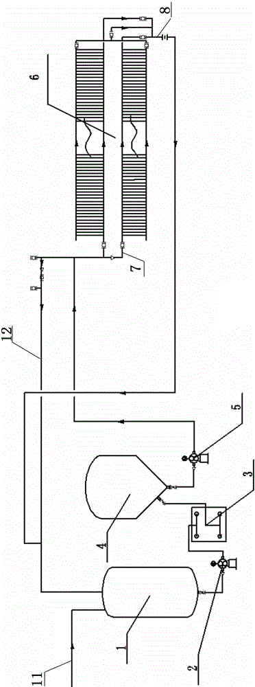
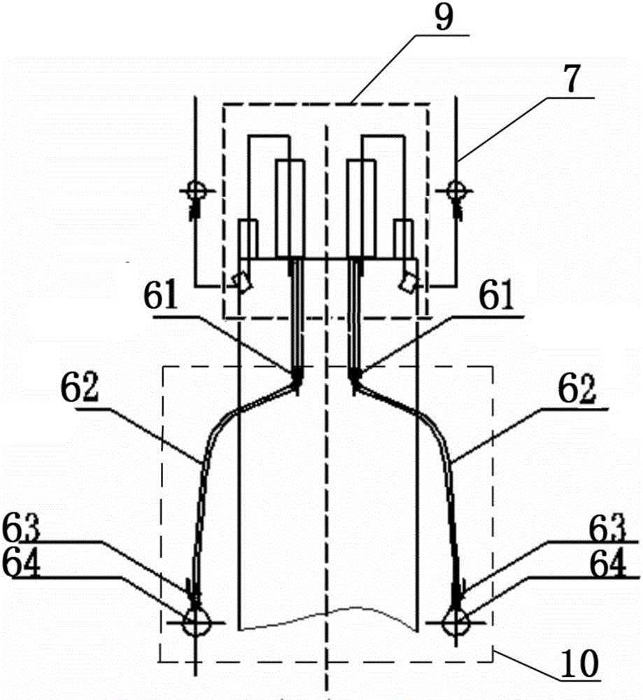
[0016] The following combination figure 1 and figure 2 The mold structure shown illustrates the specific implementation process of the present invention.

[0017] figure 1 In the spinning slurry discharge circulation pipeline system, the slurry made from the dissolving tank is communicated with the upper part of the slurry filter feed tank 1 through the pipeline 11, and the lower part of the slurry filter feed tank 1 passes through the pipeline and the filter delivery pump 2 It communicates with the inlet of the plate and frame filter 3. The degassing tank 4 is a sealed body composed of an upper cylinder and a lower cone. The outlet of the plate and frame filter 3 is connected to the side wall of the lower cone of the degassing tank 4 through a pipeline, and the bottom of the lower cone is connected to the spinning slurry pump 5 through a pipeline. It is communicated with the inlet pipeline of the pulping mechanism 6 of the spinning machine, and the outlet of the pulping m...


PUM


Abstract

The invention discloses a spinning slurry blowing circular pipeline system. The spinning slurry blowing circular pipeline system comprises a slurry filtering material supplying groove, a deaeration groove, a spinning machine blowing mechanism, pipelines and a valve. The lower portion of the slurry filtering material supplying groove is communicated with an inlet of a sheet frame filtering machine through the pipeline and a filter conveying pump. An outlet of the sheet frame filtering machine is communicated with the lower conical side wall of the deareation groove through the pipeline, and the lower conic bottom portion of the deareation groove is connected with the spinning slurry pump through the pipeline and then communicated with an inlet of the spinning machine blowing mechanism. Contact of a worker with acetone air can be reduced, damage to a human body is reduced, and the problems of manual power-on slurry dragging, slurry purifying and slurry toppling are solved; labor intensity of machine power-on is greatly lessened, the driving speed is much higher and working efficiency is improved. Slurry backflow is avoided, operation is simple, using is quick and convenient, the spinning slurry blowing circular pipeline system is safer under the working environment with the acetone gas, when production is conducted normally and channel positions are changed, pre-blowing is not needed, spinneret cap cleaning is directly conducted and head breaking covering time can be effectively controlled.

Description

technical field [0001] The invention relates to a slurry discharge technology in the technical field of spinning, in particular to a spinning slurry discharge circulation pipeline system. Background technique [0002] The main raw materials for the production of cellulose acetate tow for cigarettes are diacetate sheets, acetone, water and auxiliary raw materials mineral oil and titanium dioxide, which are dissolved to make a slurry, filtered, defoamed, and transported to the spinning machine through the spinning slurry pump. The slurry is metered by the metering pump on the spinning machine, filtered by the candle filter, preheated by the preheater, and sprayed in the tunnel of the spinning machine through the spinneret cap. After using the spare channel or parking for maintenance, the slurry pipe before the spinneret has not flowed for a long time, and the acetone in the slurry preheater volatilizes, causing the slurry to block the slurry preheater pipeline and damage the m...

Claims


Application Information

Patent Timeline
Patent Type & Authority Patents(China)
IPC IPC(8): D01D1/02D01D13/02
Inventor 赵延歌
Owner 焦作金叶醋酸纤维有限公司
Features
  • R&D
  • Intellectual Property
  • Life Sciences
  • Materials
  • Tech Scout
  • Unparalleled Data Quality
  • Higher Quality Content
  • 60% Fewer Hallucinations
Learn More