A control method for a multi-inverter system resonance suppression device

A multi-inverter, resonance suppression technology, applied in harmonic reduction devices, AC networks to reduce harmonics/ripples, single-network parallel feeding arrangements, etc., to achieve easy implementation, simple and effective resonance phenomena, and suppression of resonance phenomena Effect

Active Publication Date: 2016-03-09
HEFEI UNIV OF TECH
View PDF3 Cites 4 Cited by
  • Summary
  • Abstract
  • Description
  • Claims
  • Application Information

AI Technical Summary

Problems solved by technology

[0004] In order to solve the multi-inverter system resonance problem without changing the software and hardware configuration of each inverter in the multi-inverter system, the present invention provides a control method for a multi-inverter system resonance suppression device

Method used


Image

  • A control method for a multi-inverter system resonance suppression device
  • A control method for a multi-inverter system resonance suppression device
  • A control method for a multi-inverter system resonance suppression device

Examples


Embodiment Construction

[0027] The following describes the implementation of the present invention with specific examples in conjunction with the accompanying drawings.

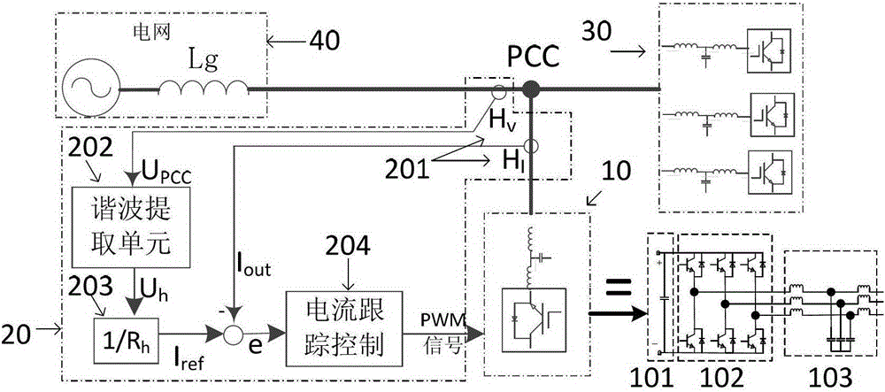
[0028] figure 1 Shown is a structural principle diagram of the multi-inverter system resonance suppression device circuit and control method proposed by the present invention. A multi-inverter system resonance suppression device provided by the present invention includes a voltage source inverter 10 and its control system 20. The voltage source inverter includes a DC side 101, a power switch tube 102, and an LCL output Filter 103, the control system 20 includes a sampling unit 201, a harmonic extraction unit 202, a command current calculation unit 203 and a current tracking control unit 204, and the control system 20 calculates the PWM switch according to the voltage signal and current signal obtained by sampling. The drive signal is sent to the voltage source inverter 10, and the voltage source inverter 10 controls its power switc...


PUM


Abstract

The invention discloses a multi-inverter system resonance restraining device and a controlling method thereof. The multi-inverter system resonance restraining device is connected to a point of common coupling (PCC) of a multi-inverter system. According to the multi-inverter system resonance restraining device, only PCC voltage needs to be sampled, PCC current signals do not need to be sampled, and software and hardware configuration of each inverter in a multi-inverter system does not need to be modified; and the controlling method of the multi-inverter system resonance restraining device has the basic principle that the multi-inverter system resonance restraining device is virtualized into one resistor working at all resonance frequency bands to restrain the resonance phenomenon of the multi-inverter system, and the method is simple, effective and feasible.

Description

technical field [0001] The invention relates to the field of new energy power generation, in particular to a control method for a resonance suppressing device used to suppress the resonance of a parallel system of multiple new energy interface inverters. Background technique [0002] With the rapid growth of the new energy power generation industry such as solar power generation systems, the application of new energy interface inverters is becoming more and more extensive, and the application scale is increasing. The number of parallel inverters in the same new energy power generation system gradually increase. However, the stability of the multi-inverter system will decrease with the increase of the number of parallel inverters, especially the inverter with LCL output filter, which will easily cause the resonance of the multi-inverter system. The multi-inverter system resonance problem has made the reliable and stable operation of the power generation system and power grid...

Claims


Application Information

Patent Timeline
Patent Type & Authority Patents(China)
IPC IPC(8): H02J3/01H02J3/38
CPCY02E40/40
Inventor 张兴李飞朱虹王付胜谢震杨淑英
Owner HEFEI UNIV OF TECH
Why Eureka
Try Eureka