
Synchronous chamfering device and gear hobbing machine

A gear hobbing machine and chamfering technology, applied in the direction of feeding device, gear tooth manufacturing device, gear teeth, etc., can solve the problems of large working space, high labor intensity, low efficiency, etc., and achieve improved efficiency and speed, simple structure, and reduced The effect of working area

Inactive Publication Date: 2013-11-27
SANY GRP
View PDF10 Cites 8 Cited by
  • Summary
  • Abstract
  • Description
  • Claims
  • Application Information

AI Technical Summary

Problems solved by technology

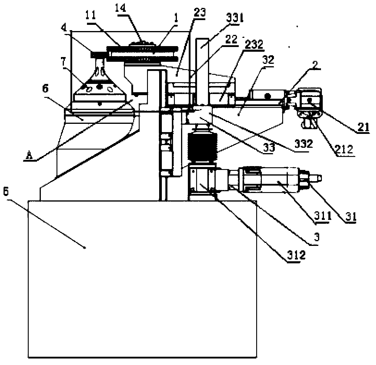
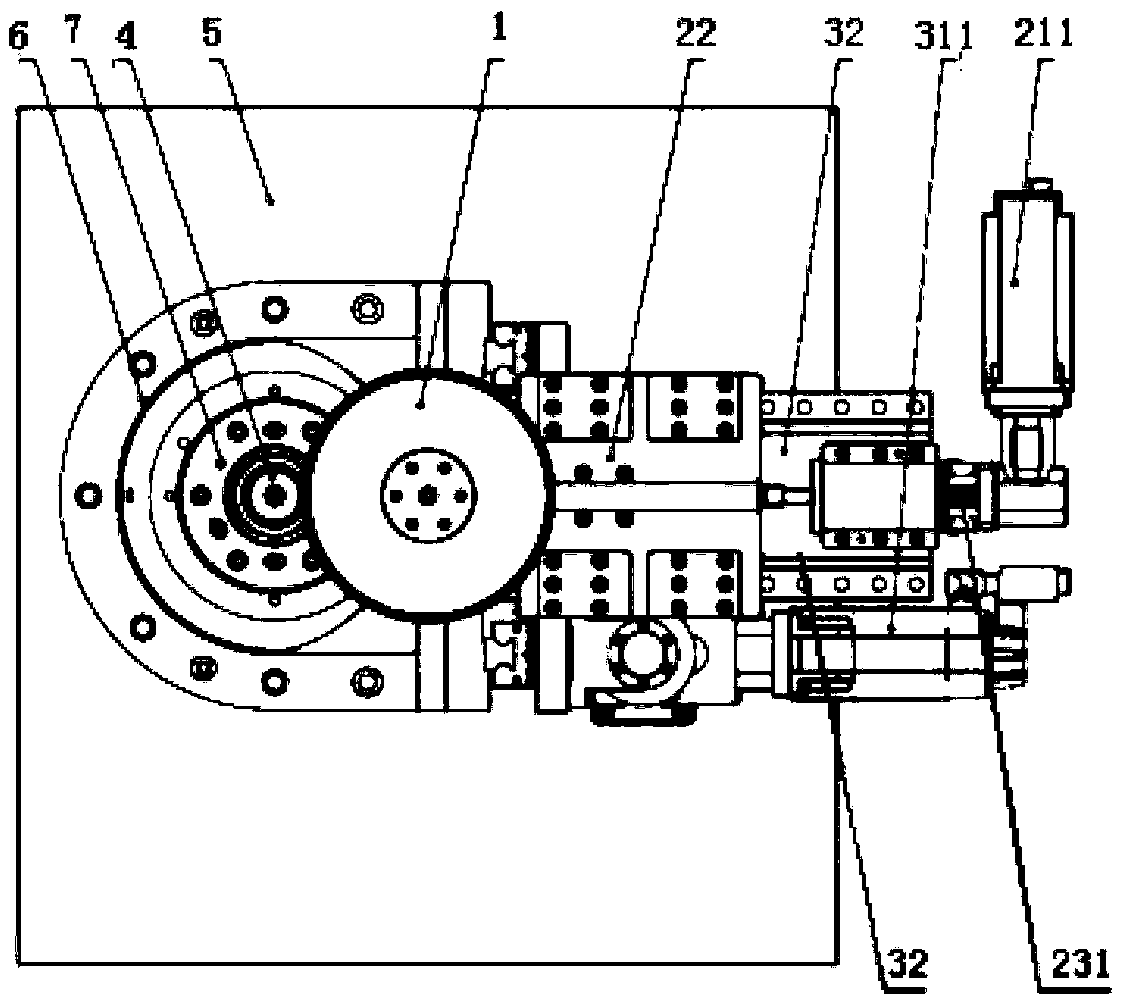
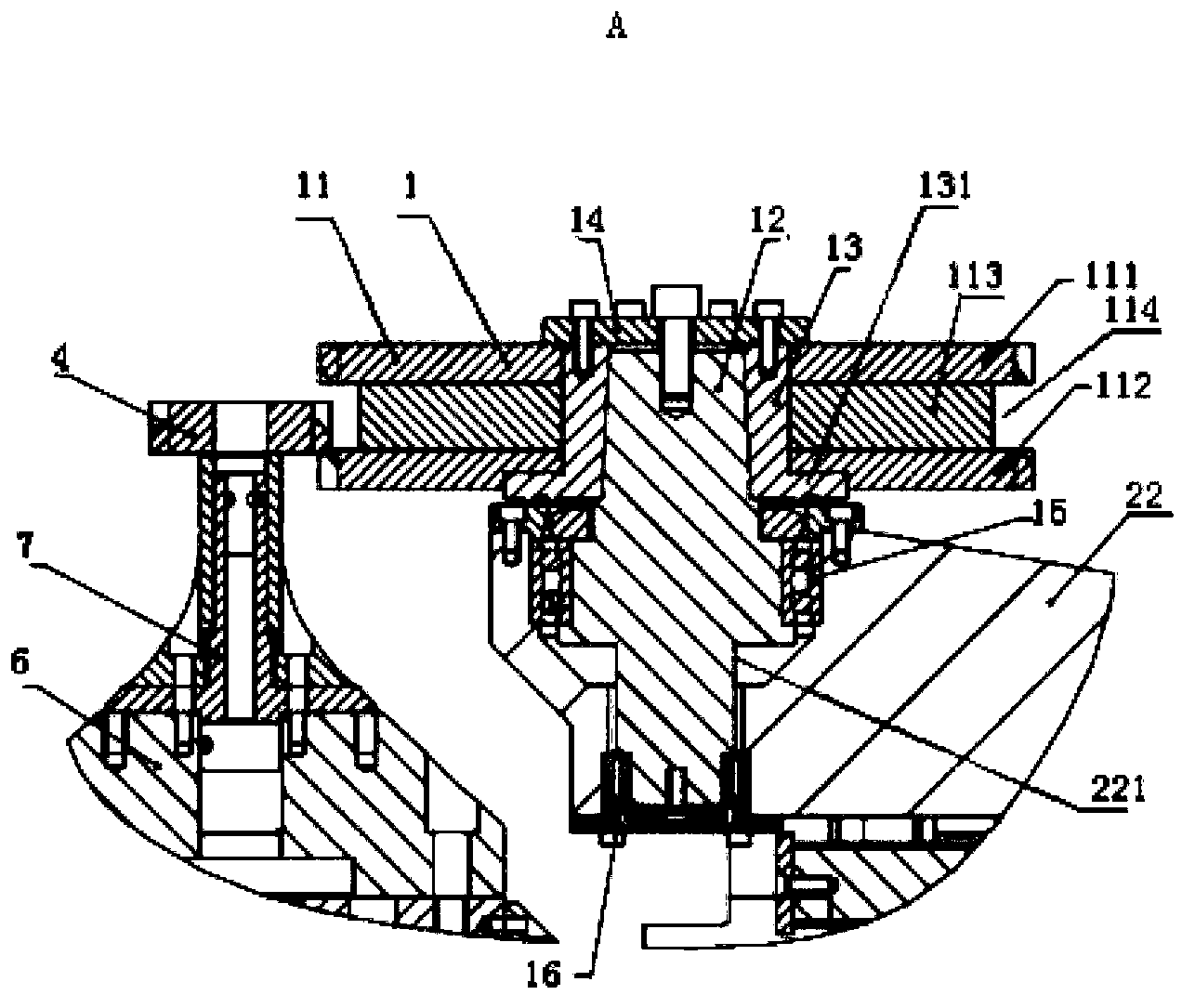
[0005] In view of this, the present invention proposes a synchronous chamfering device and gear hobbing machine to solve the problem of poor quality, high labor intensity and low efficiency of manual deburring and chamfering; Deburring and chamfering of gears with modulus and tooth width

Method used


Image

  • Synchronous chamfering device and gear hobbing machine
  • Synchronous chamfering device and gear hobbing machine
  • Synchronous chamfering device and gear hobbing machine

Examples


Embodiment Construction

[0067]The following will clearly and completely describe the technical solutions in the embodiments of the present invention with reference to the accompanying drawings in the embodiments of the present invention. Obviously, the described embodiments are only some, not all, embodiments of the present invention. Based on the embodiments of the present invention, all other embodiments obtained by persons of ordinary skill in the art without creative efforts fall within the protection scope of the present invention.

[0068] It should be noted that, in the case of no conflict, the embodiments of the present invention and the features in the embodiments can be combined with each other.

[0069] The basic idea of ​​the present invention is to design a synchronous chamfering device, which can efficiently complete different Deburring and chamfering of gears with modulus and tooth width.

[0070] Below in conjunction with accompanying drawing, each preferred embodiment of the present...


PUM


Abstract

The invention discloses a synchronous chamfering device and a gear hobbing machine. A working platform is arranged on a machine body, and a workpiece is fixed on the working platform through a clamping gear of a clamp; the working platform and a cutting tool rotate and cut the workpiece to obtain the gear with burrs; the synchronous chamfering device comprises a cutter body, an X-axis moving device and a Z-axis moving device, wherein the cutter body is in contact with the burrs of the gear and used for grinding the burrs and chamfering the gear; the X-axis moving device is connected with the cutter body and used for enabling the cutter body to move in the X-axis direction; the Z-axis moving device is fixed on the machine body, is connected with the X-axis moving device and used for enabling the X-axis moving device to drive the cutter body to move in the Z-axis direction perpendicular to the X-axis direction. The synchronous chamfering device has the advantages that the efficiency and the speed that the synchronous chamfering device removes and chamfers the burrs are improved; the structure is simple, the unused space of the gear hobbing machine is fully utilized, and the working area of the synchronous chamfering device is reduced; the burrs can be removed and chamfered from gears with different number of dies and tooth widths.

Description

technical field [0001] The invention relates to a precision gear processing device, in particular to a synchronous chamfering device and a gear hobbing machine. Background technique [0002] Gear hobbing machine is the most widely used machine tool in gear processing machine tools. Straight teeth, helical cylindrical gears, etc. can be cut on the gear hobbing machine; Burrs and flanging to the inside of the tooth surface will remain. If these burrs and edges are not treated, the honing and grinding of the gear after heat treatment and hardening will seriously damage the honing wheel. The existing deburring and chamfering measures mainly include: [0003] 1. Manually use files or grinding wheels to deburr and chamfer the gears. This method has low efficiency, poor chamfering quality and high labor intensity. [0004] 2. Grinding wheel chamfering machine, this method has improved efficiency, but the equipment cost is high, the work takes up a lot of space, and it is impossi...

Claims


Application Information

Patent Timeline
Patent Type & Authority Applications(China)
IPC IPC(8): B23F19/12B23F21/00B23Q5/40
Inventor 詹文良朱世春马化韬
Owner SANY GRP
Learn More