
Automatic camshaft assembling machine

A technology for assembly machines and camshafts, which is applied to assembly machines, metal processing equipment, manufacturing tools, etc., and can solve problems such as low production efficiency

Active Publication Date: 2013-11-27
宁波江宸智能装备股份有限公司
View PDF6 Cites 42 Cited by
  • Summary
  • Abstract
  • Description
  • Claims
  • Application Information

AI Technical Summary

Problems solved by technology

At present, when the pipe fittings, cams and flanges are assembled on the assembly machine, the pipe fittings, cams and flanges are generally placed on the assembly machine manually, so the production efficiency is relatively low

Method used


Image

  • Automatic camshaft assembling machine
  • Automatic camshaft assembling machine
  • Automatic camshaft assembling machine

Examples


Embodiment Construction

[0063] The present invention will be described in further detail below in conjunction with the accompanying drawings and specific embodiments.

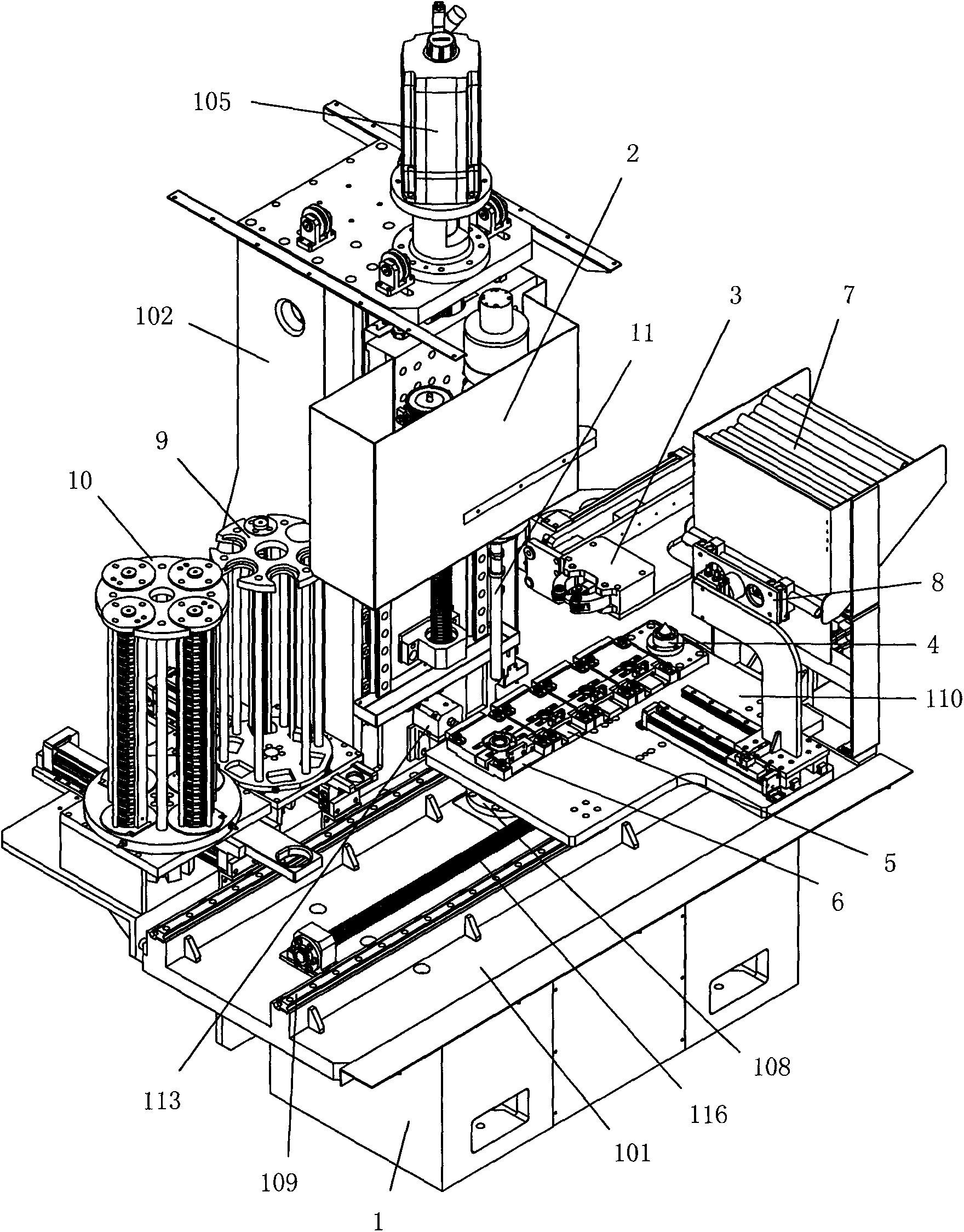
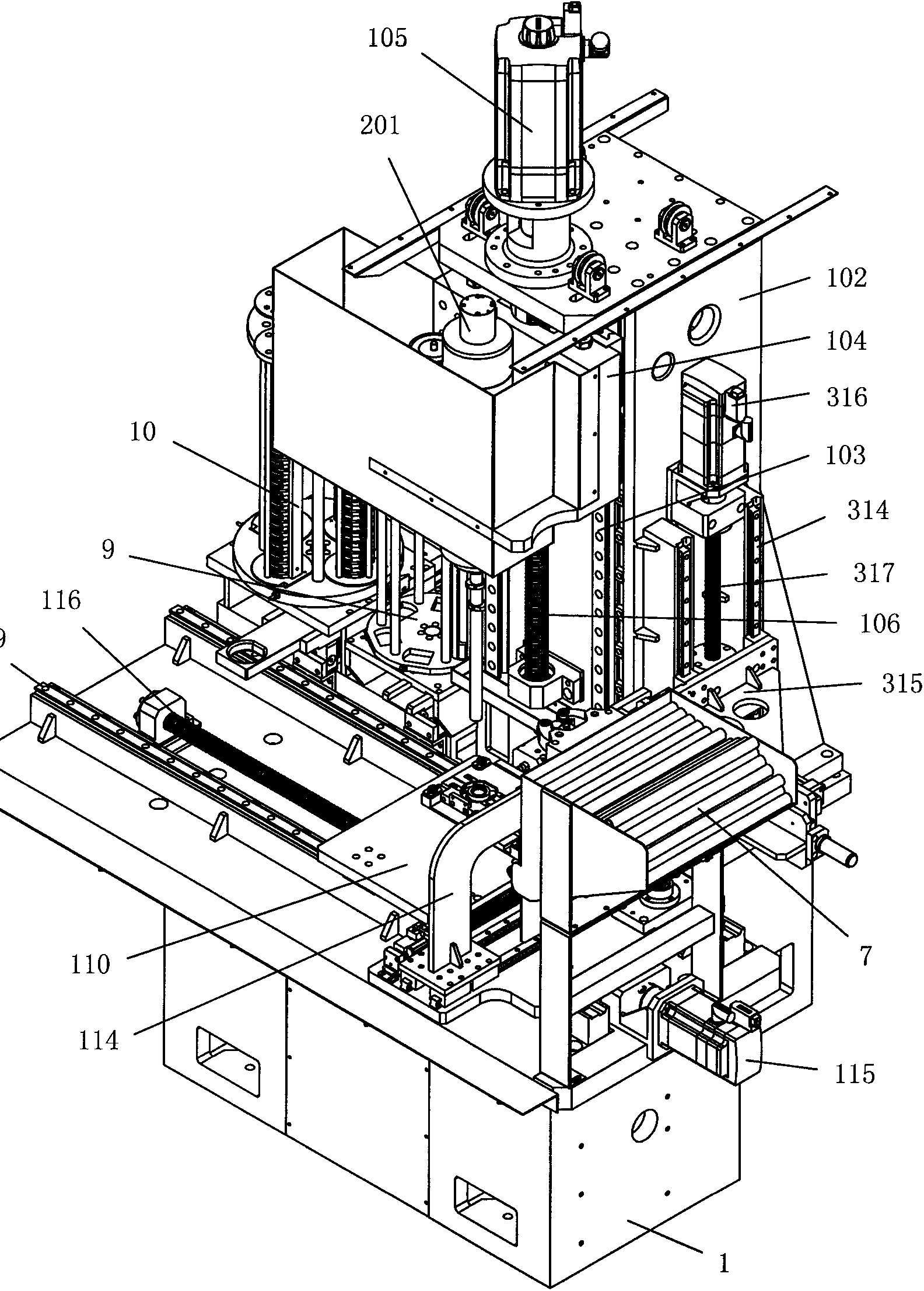
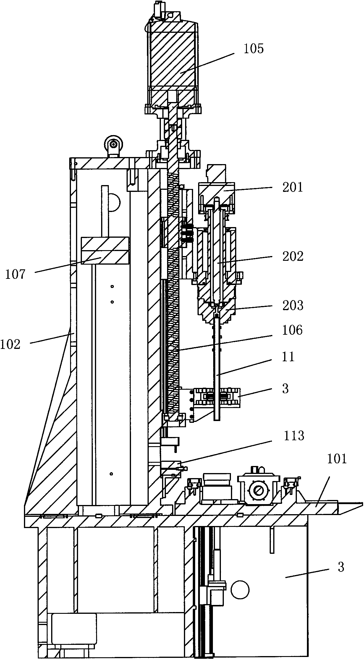
[0064] refer to Figure 1 to Figure 16 , an automatic assembly machine for camshafts, comprising a frame 1, a workbench 101 arranged on the frame 1, a column 102 is arranged on the workbench 1, and a column 102 for clamping pipe fittings is vertically slid on the column 102 And drive the clamping and rotating mechanism 2 that rotates the pipe fittings. The clamping and rotating mechanism 2 is driven by a vertical driving mechanism to move up and down relative to the column 102. The vertical driving mechanism includes a vertically arranged on the column 101 The vertical transfer guide rail 103, the vertical transfer guide rail 103 is slid with a vertical slide plate 104, the clamping rotation mechanism 2 is fixed on the vertical slide plate 104, and the upper end of the column 102 is provided with a vertical movement motor 105, the ou...


PUM


Abstract

An automatic camshaft assembling machine comprises a frame, a worktable and a stand column. A clamping and rotating mechanism for clamping a pipe and driving the pipe to rotate is vertically and slidably arranged on the stand column. A knurling mechanism capable of moving to the position just below the clamping and rotating mechanism is arranged on one side of the clamping and rotating mechanism. A sliding table is transversely and slidably arranged in the front of the clamping and rotating mechanism. A pipe positioning clamp, cam clamping tools and a flange clamping tool are sequentially and parallelly mounted on the rear portion of the sliding table. A pipe storing mechanism for storing the pipes is arranged in the front of the knurling mechanism. A mechanical arm for conveying the pipes is longitudinally and slidably arranged on the rear portion of the sliding table. A cam storing mechanism for storing cams and a cam pushing mechanism for pushing the cams are arranged on the other side of the clamping and rotating mechanism. A flange storing mechanism for storing flanges and a flange pushing mechanism for pushing the flanges are arranged on the outer side of the cam storing mechanism. By the aid of the structure, full-automatic assembling of camshafts can be realized, production efficiency is greatly improved, and labor intensity is lowered.

Description

(1) Technical field [0001] The invention relates to a camshaft automatic assembly machine. (2) Background technology [0002] The camshaft is a key part of the engine. The traditional manufacturing method is mainly forging or casting. The cam, flange and shaft are integrated, while the assembled camshaft is made of pipe fittings made of steel pipes and the cam and flange are separately manufactured, and then Then assembled as a whole, compared with the traditional manufacturing method, the assembled camshaft has the advantages of light weight, production cost, reasonable material distribution, and easy manufacturing. At present, when the pipe fittings, cams and flanges are assembled on the assembly machine, the pipe fittings, cams and flanges are generally placed on the assembly machine manually, so the production efficiency is relatively low. (3) Contents of the invention [0003] In order to overcome the above-mentioned shortcomings in the prior art, the present inventi...

Claims


Application Information

Patent Timeline
IPC IPC(8): B23P21/00B23P9/02
Inventor 李道银缪建清范迪华
Owner 宁波江宸智能装备股份有限公司
Learn More