Assembling and using method of a glass positioning vacuum suction cup

A vacuum suction cup and suction cup technology, applied in workpiece clamping devices, manufacturing tools, etc., can solve the problems of inconsistent height around the glass, uneven glass plane, adsorption deformation of the glass plane, etc., to achieve ideal positioning and adsorption effect, easy to operate, The effect of saving rubber raw materials

Active Publication Date: 2016-01-27
ZAOZHUANG HAIDI ENERGY TECH
View PDF8 Cites 0 Cited by
  • Summary
  • Abstract
  • Description
  • Claims
  • Application Information

AI Technical Summary

Problems solved by technology

For glass below 5mm, after the rubber gasket is vacuumed, it is easy to absorb and deform the glass plane, resulting in inconsistent heights around the glass. During the grinding process of the grinding head, some sides can be ground, and some sides cannot be ground. Very high scrap rate
[0003] The patent document with the application number of 201220547172.7 discloses a glass suction cup with strong adsorption force, which is mainly used for absorbing thick glass, which is convenient for processing and transportation. For absorbing glass below 5mm, it will cause uneven glass surface and make the glass scrap

Method used


Image

  • Assembling and using method of a glass positioning vacuum suction cup
  • Assembling and using method of a glass positioning vacuum suction cup
  • Assembling and using method of a glass positioning vacuum suction cup

Examples


Embodiment 1

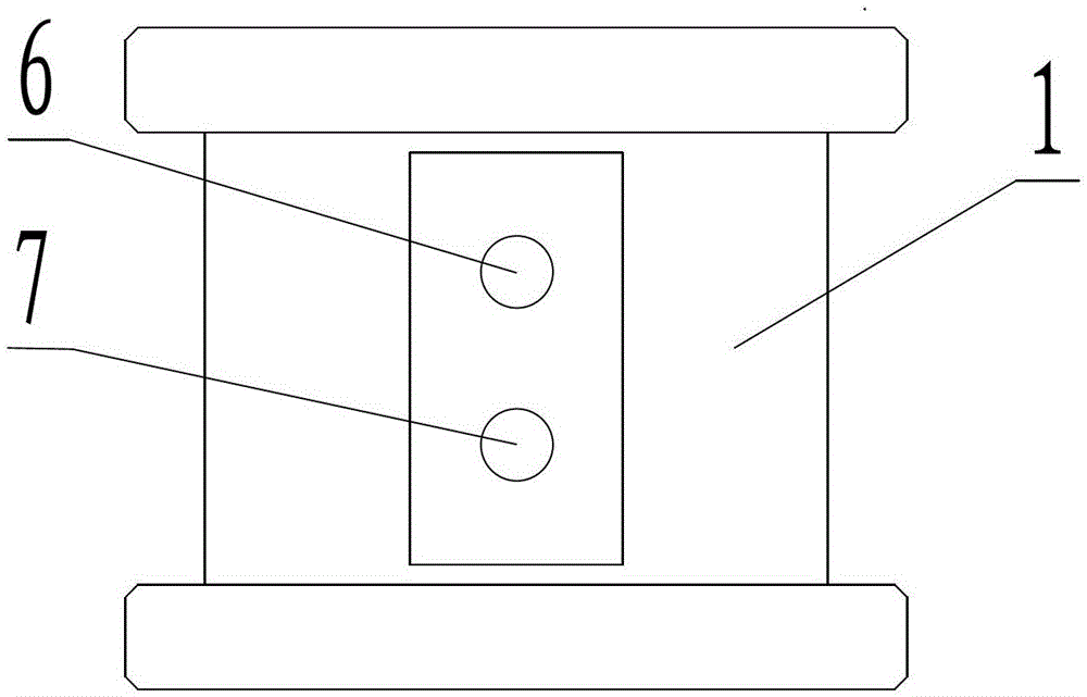
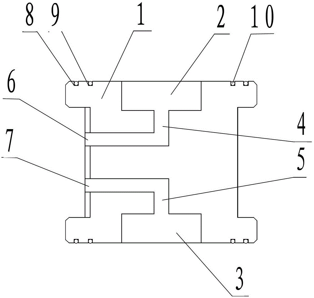
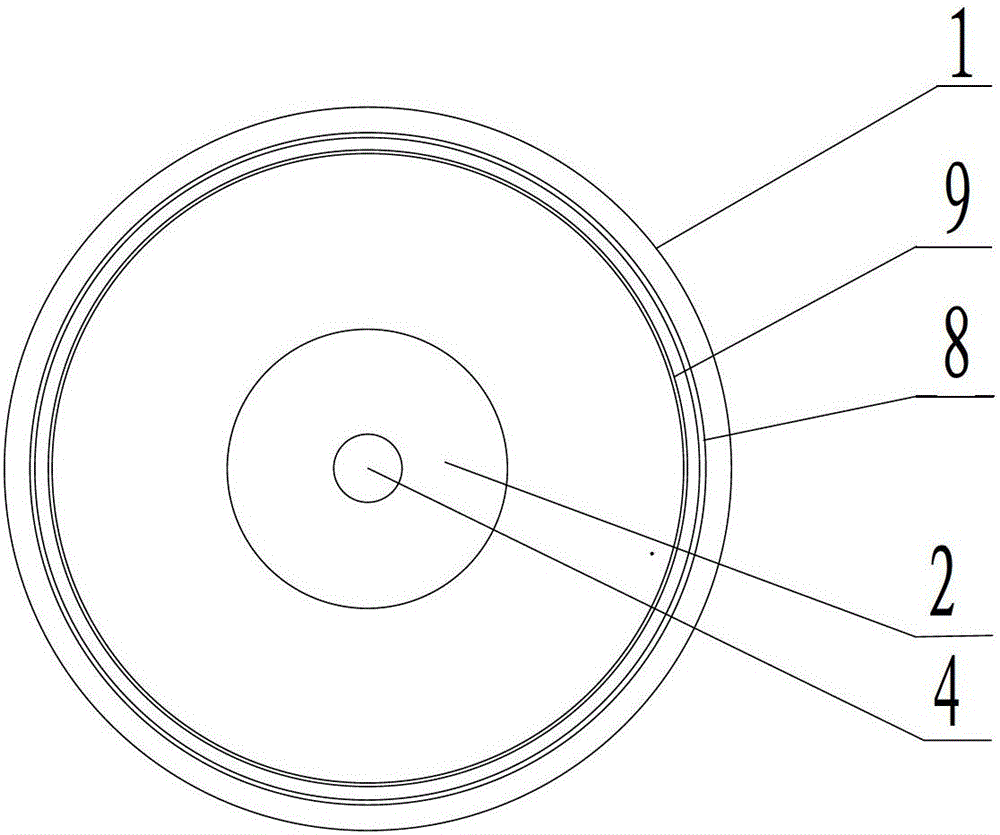
[0024] The sucker body 1 is cast into an I-shaped structure, the upper middle part of the sucker body 1 is processed into a cylindrical upper vacuum chamber 2, and the lower middle part is processed into a cylindrical lower vacuum chamber 3.

Embodiment 2

[0026] The center of the upper vacuum chamber 2 is drilled downwards to form a channel, and the outer wall of the suction cup body 1 is drilled at the corresponding position at the bottom of the channel to form a channel. The two channels communicate to form an inverted L-shaped upper vacuum channel 4. Install the upper joint 6; the center of the lower vacuum chamber 3 is drilled upwards to form a channel, the outer wall of the suction cup body 1 and the corresponding part of the top and bottom of the channel are drilled to form a channel, and the two channels are connected to form a reverse inverted L-shaped lower vacuum channel 5, and the lower vacuum channel 5 The lower joint 7 is installed at the port corresponding to the outer wall of the suction cup body 1; the upper joint 6 and the lower joint 7 are butted and installed with the vacuum pump through two vacuum tubes.

Embodiment 3

[0028] The upper plane and the lower plane of the suction cup body 1 respectively process the first annular sealing groove 8 and the second annular sealing groove 9. During processing, the second annular sealing groove 9 is located inside the first annular sealing groove 8, and the upper plane and the lower plane of the suction cup body 1 are processed at least 2 Ring ring seal groove.


PUM


Abstract

Provided is a glass location vacuum pad assembly and use method. A glass location vacuum pad is formed by a pad body, an upper vacuum cavity, a lower vacuum cavity, an upper vacuum channel, a lower vacuum channel, an upper connector, a lower connector, a first annular sealing groove, a second annular sealing groove and O-shaped sealing ring pads. The pad body is cast to be of an I-shaped structure, the cylindrical upper vacuum cavity is processed in the middle of the upper portion of the pad body, the cylindrical lower vacuum cavity is processed in the middle of the lower portion, at least two annular sealing grooves are formed in the upper plane and the lower plane of the pad body, and the O-shaped sealing ring pads are installed in the annular sealing grooves correspondingly. The glass location vacuum pad is simple and efficient in structure design, ideal in location and attraction effect, convenient to manufacture, simple in operation, capable of reducing labor intensity of operators, low in manufacture cost, capable of saving rubber raw materials, easy to operate, convenient to maintain, flexible in operation and suitable for popularization and use.

Description

technical field [0001] The invention relates to the technical field of suction cups, in particular to a method for assembling and using a glass positioning vacuum suction cup. Background technique [0002] At present, the suction cups used on glass processing equipment at home and abroad use upper and lower rubber gaskets, and the vacuum is pumped to make the upper rubber gasket absorb the glass and the lower rubber gasket to absorb the platform, and then use the grinding head to grind the surroundings of the glass and special-shaped glass. For glass below 5mm, after the rubber gasket is vacuumed, it is easy to absorb and deform the glass plane, resulting in inconsistent heights around the glass. During the grinding process of the grinding head, some sides can be ground, and some sides cannot be ground. The scrap rate is extremely high. [0003] The patent document whose application number is 201220547172.7 discloses a glass suction cup with strong adsorption force, which i...

Claims


Application Information

Patent Timeline
Patent Type & Authority Patents(China)
IPC IPC(8): B25B11/00
Inventor 刘铁龙
Owner ZAOZHUANG HAIDI ENERGY TECH
Why Eureka
Try Eureka