Double crankshaft self-balancing internal combustion engine and driving unit thereof

A driving unit and self-balancing technology, which is applied in the direction of machines/engines, transmissions, mechanical equipment, etc., to achieve the effects of convenient manufacture, increased power, and good carrying capacity

Inactive Publication Date: 2013-11-27
福建省飞驰科技股份有限公司
View PDF22 Cites 2 Cited by
  • Summary
  • Abstract
  • Description
  • Claims
  • Application Information

AI Technical Summary

Problems solved by technology

[0006] The present invention aims at the above-mentioned problems existing in the existing technology, and provides a dual crankshaft self-balancing internal combustion engine and its drive unit. The technical problem to be solved by the present invention is: how to balance the vibration problem caused by the large-mass piston driving the large-mass crankshaft

Method used


Image

  • Double crankshaft self-balancing internal combustion engine and driving unit thereof
  • Double crankshaft self-balancing internal combustion engine and driving unit thereof
  • Double crankshaft self-balancing internal combustion engine and driving unit thereof

Examples


Embodiment 1

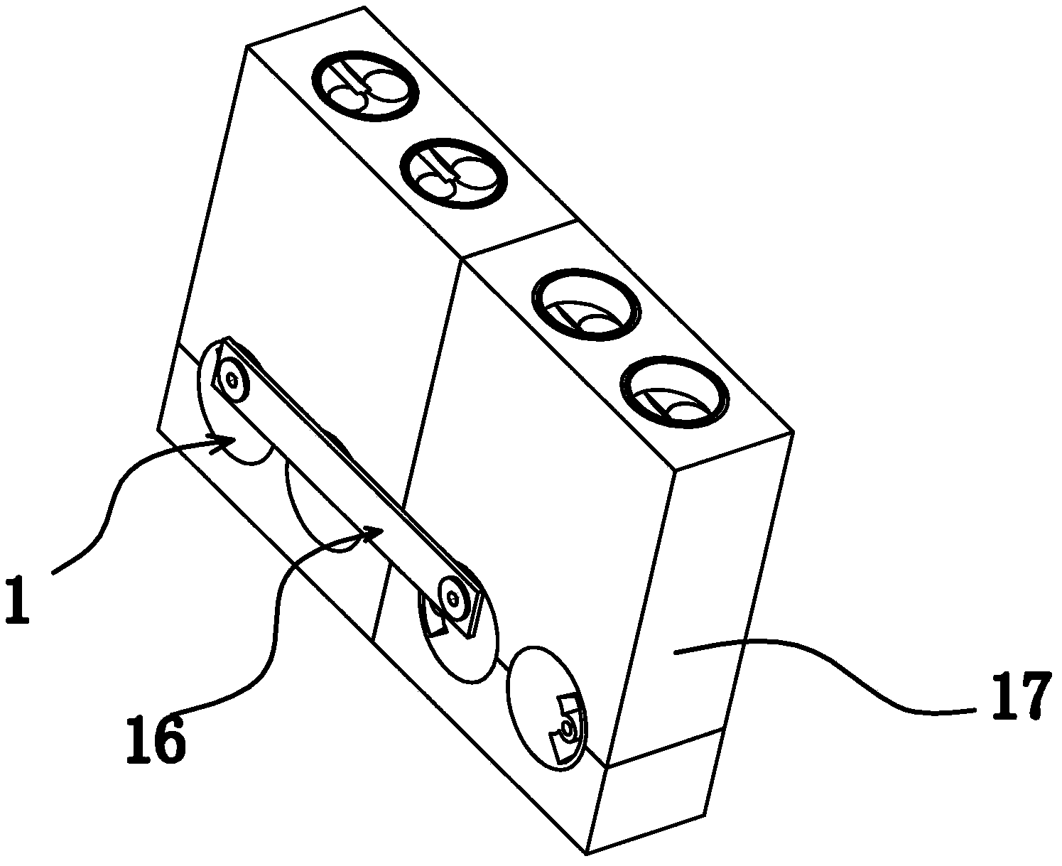
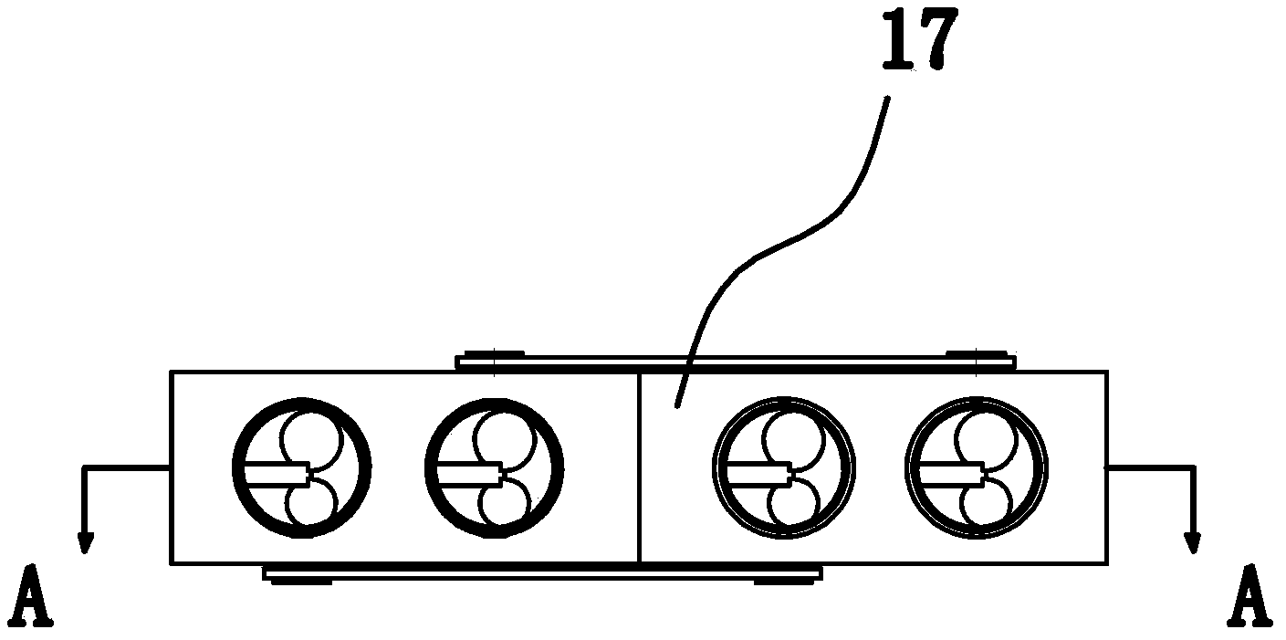
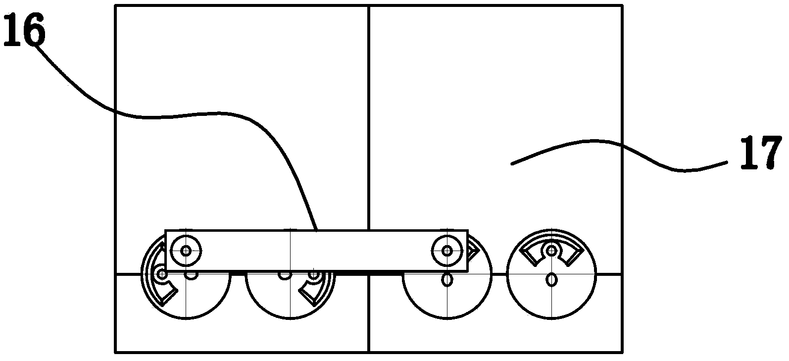
[0057] Such as Figure 1-Figure 7 As shown, the double crankshaft self-balancing internal combustion engine includes a casing 17, and several drive units 1 are arranged in the casing 17. As a preferred solution, the drive unit 1 includes a pair of identical cylinders 2 and a pair of identical crankshafts 3, each Each cylinder 2 has a piston 4 and each crankshaft 3 has a journal 5 . The advantage is that the mass of the crankshaft 3 is too large. After segmentation, one cylinder 2 corresponds to a lower crankshaft 3, and the shape and weight of a single crankshaft 3 become smaller, which is easy to process. A crankshaft 3 for transmission corresponds to a multi-cylinder body. A present crankshaft 3 corresponds to a single cylinder, and multiple pairs of single cylinder drive units 1 are combined to form an engine array, which greatly increases the power of the internal combustion engine. A crankshaft 3 corresponds to the position of a cylinder 2 respectively. There is a piston...

Embodiment 2

[0075]The general content of this embodiment is the same as that of Embodiment 1, the difference is that in this embodiment, as another solution, the transmission mechanism 7 includes a piston rod 9, a sliding frame 10 and a sliding block 11, and the middle part of the sliding block 11 is provided with a A mounting hole 12 whose caliber matches the diameter of the journal 5, and the journal 5 is inserted in the mounting hole 12. When the crankshaft 3 rotates, the journal 5 will drive the slider 11 to move synchronously. At the same time, the journal 5 and the inner wall of the mounting hole 12 will rotate, and the force relationship between the journal 5 and the slider 11 will be improved by using the plugging method. Stable without impact.

[0076] The upper end of the piston rod 9 is fixedly connected with the piston 4, and the lower end of the piston rod 9 is fixedly connected with the sliding frame 10. The sliding frame 10 is provided with a chute 18 along the radial direc...

Embodiment 3

[0080] Such as Figure 22 As shown, the general content of this embodiment is the same as that of Embodiment 2, the difference is that in this embodiment, as another solution, each crankshaft 3 corresponds to two cylinders 2, and when in use, both the crankshaft 3 and the cylinder 2 The axis is laid horizontally along the horizontal direction. The two cylinders 2 are located at both ends of the crankshaft 3 and are symmetrically distributed. The piston 4 of each cylinder 2 is fixedly connected to a piston rod 9, and the two pistons corresponding to a crankshaft 3 The rods 9 are fixedly connected to the front and rear ends of the slide frame 10 respectively, and the two piston rods 9 are located on the same axis. In the present embodiment, the piston stroke is 93mm, and the weight of the crankshaft 3 is 55 kilograms. The advantage of this embodiment is that since a crankshaft is provided with a cylinder 2 at the front and rear ends, the piston rod 9 has a force on both ends of...


PUM


Abstract

The invention provides a double crankshaft self-balancing internal combustion engine and a driving unit thereof and belongs to the technical field of internal combustion engine devices. According to the double crankshaft self-balancing internal combustion engine and the driving unit of the double crankshaft self-balancing internal combustion engine, the problem of vibration caused by the fact that a high-mass piston drives a high-mass crankshaft in the prior art is effectively solved. The internal combustion engine comprises the driving unit. The driving unit comprises a pair of identical cylinders and a pair of identical crankshafts, one crankshaft corresponds to the position of one cylinder respectively, pistons are positioned in the cylinders, the crankshafts are provided with shaft necks, the axes of the two crankshafts are parallel and are arranged side by side, a first linkage mechanism which enables the two crankshafts to keep rotating in opposite directions at the same rotating speed and can transmit radial force for the two crankshafts is arranged between the two crankshafts, a transmission mechanism capable of converting linear motion of the pistons into circumferential rotation of the shaft necks is arranged between the shaft necks and the corresponding pistons, and the shaft necks positioned on the two crankshafts are symmetrically distributed. According to the double crankshaft self-balancing internal combustion engine and the driving unit of the double crankshaft self-balancing internal combustion engine, the problem that a single crankshaft in a large internal combustion engine vibrates easily is effectively solved, and the load bearing capability is good.

Description

technical field [0001] The invention belongs to the technical field of internal combustion engine equipment, and relates to an internal combustion engine, in particular to a dual crankshaft self-balancing internal combustion engine. Background technique [0002] Usually said internal combustion engine refers to piston type internal combustion engine, and piston type internal combustion engine is the most general with reciprocating piston type. The piston-type internal combustion engine mixes fuel and air and burns it in its cylinder, and the heat energy released makes the cylinder generate high-temperature and high-pressure gas. The expansion of the gas pushes the piston to do work, and then the mechanical work is output through the crank connecting rod mechanism or other mechanisms to drive the driven machine to work. [0003] The internal combustion engine generally includes a housing, in which a crankshaft and a piston are arranged, the piston is placed in the combustion...

Claims


Application Information

Patent Timeline
Patent Type & Authority Applications(China)
IPC IPC(8): F02B75/32F16H21/18
Inventor 何学文
Owner 福建省飞驰科技股份有限公司
Why Eureka
Try Eureka