
Hydraulic chain tensioner

A tensioner, hydraulic technology, applied in belt/chain/gear, mechanical equipment, transmission, etc., can solve the problems of occupying engine space, low added value, and high noise of the tensioner, and achieve a one-way sealing structure. Good effect, better wear resistance, good sealing effect

Inactive Publication Date: 2013-11-27
JIANGSU SIXIANG SILK
View PDF5 Cites 4 Cited by
  • Summary
  • Abstract
  • Description
  • Claims
  • Application Information

AI Technical Summary

Problems solved by technology

This will lead to an increase in engine size and load, resulting in a decrease in fuel efficiency. Therefore, in terms of structure, performance, and economy, traditional hydraulic tensioners have the following obvious shortcomings:
[0005]1. There are many components and the system is complicated, occupying a considerable size of the engine space, which is not convenient for the miniaturization of the engine;
[0006]2. The use of external oil supply increases the number of sealing points in the system, and the reliability is reduced due to the material and life of rubber and other seals;
[0007]3. The high price of the tensioner is not conducive to promoting the development of VVT engines in the direction of miniaturization, high performance and low cost;
[0008]4. The tensioner is noisy and has poor reliability, making it difficult to meet the high requirements of VVT engines
Although the structure is simple and the cost is low, because the product has been launched for many years and the added value is low, it is difficult to generate good economic benefits;

Method used


Image

  • Hydraulic chain tensioner
  • Hydraulic chain tensioner
  • Hydraulic chain tensioner

Examples


Embodiment Construction

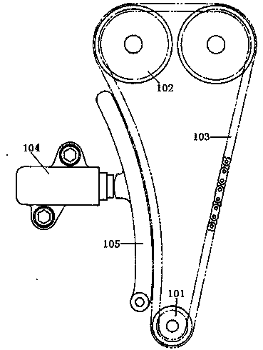
[0031] see figure 1 , shows the hydraulic chain tensioner of the present invention.

[0032] The transmission chain 103 between the drive sprocket 101 and the driven sprocket 102 installed on the crankshaft of the engine is tensioned by the hydraulic chain tensioner 104 through the arc pressure plate 105, and the hydraulic chain tensioner 104 is installed on on the engine body of the vehicle.

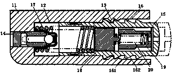
[0033] see figure 2 , showing the specific structure of the hydraulic chain tensioner 104, the hydraulic chain tensioner 104 includes a cylinder 11 with an open front end, and the cylinder 11 is provided with a front opening that can move along the inner surface of the cylinder 11 The plunger 15, the rear side of the plunger 15 is provided with a hydraulic chamber 12, the rear end of the cylinder 11 is provided with an oil inlet, the oil inlet is connected with an oil injection chamber 14, and the oil injection chamber 14 A one-way valve is provided to provide one-way oil inlet of t...


PUM


Abstract

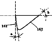
A hydraulic chain tensioner comprises a cylinder with an opening at the front end, a plunger with an opening at the front end and capable of moving along the inner surface of the cylinder is arranged in the cylinder, a hydraulic cavity is formed in the rear side of the plunger, an oil inlet is arranged at the back end of the cylinder and communicated with an oil injection chamber, a one-way valve for providing one-way oil injection for the oil inlet is disposed in the oil injection chamber, an inner thread is arranged on the inner surface of the front end of the cylinder, an outer thread matched with the inner thread is arranged on the plunger and comprises a clamping surface and a deviating surface, the angle formed by the clamping surface and the longitudinal perpendicular line is smaller than that formed by the deviating surface and the longitudinal perpendicular line, a first compression spring is placed in the hydraulic cavity of the cylinder, one end of the first compression spring abuts against the bottom of the hydraulic cavity, and the other end of the first compression spring abuts against the plunger. The hydraulic chain tensioner is simple in structure, convenient to assemble and disassemble, good in tensioning effect and capable of effectively providing continuous and stable tensioning pressure for timing belts, timing chains and the like to improve the stability of vehicles.

Description

technical field [0001] The invention relates to the tensioning technology of vehicle belts, in particular to a hydraulic chain tensioner. Background technique [0002] The timing belt of the engine needs to be provided with a tensioning effect to guide and tighten it so that it is always in the best tensioned state. [0003] The main structural form of the traditional hydraulic tensioner is that the tensioner cylinder body relies on the external oil supply of the engine to work, and the oil passage needs to be arranged on the engine, and the spring force is the minimum tension force of the pre-tensioned belt in the stop state, which plays a major role in the work. The most important is the oil pressure from the engine oil supply system. [0004] As more and more devices such as VVT systems use oil pressure to work, the consumption of lubricating oil in the engine continues to increase. To supply sufficient lubricating oil to the engine, the oil pump size needs to be increa...

Claims


Application Information

Patent Timeline
IPC IPC(8): F16H7/08
Inventor 金春来
Owner JIANGSU SIXIANG SILK
Learn More