Method and device for inspection measurement of fan-shaped section base of continuous casting machine

A continuous casting machine segment and measurement method technology, which is applied in the direction of measuring device, mechanical gap measurement, height/level measurement, etc., can solve the problems of affecting the measurement adjustment accuracy, inconvenient measurement distance, and many obstacles, so as to improve construction Quality, simple structure, and the effect of improving the speed of measurement adjustment

Active Publication Date: 2013-11-27
CHINA THIRD METALLURGICAL GRP
View PDF4 Cites 11 Cited by
  • Summary
  • Abstract
  • Description
  • Claims
  • Application Information

AI Technical Summary

Problems solved by technology

The traditional method of measuring and adjusting the sector base is to use a level, theodolite or infrared rangefinder to measure the spatial position of each sector positioning device on the sector base, and then adjust according to standard data. The advantage of this method is that it can ensure Installation accuracy, but there are many disadvantages. First, because there are many obstacles around the base of the sector (process pipes, cooling room walkways, etc.), it is very inconvenient to measure the distance between the positioning device of the sector and the tangent line of the casting machine; When using the theodolite or infrared range finder to cast the tangent line of the casting machine, the instrument needs to be shifted multiple times, and each time the shift must be re-checked with the original reference point, it is very easy to have a point error, which affects the measurement and adjustment accuracy. This kind of error can only be reflected in the arc inspection of the fan section, which is not conducive to the guarantee of the construction period

Method used


Image

  • Method and device for inspection measurement of fan-shaped section base of continuous casting machine
  • Method and device for inspection measurement of fan-shaped section base of continuous casting machine
  • Method and device for inspection measurement of fan-shaped section base of continuous casting machine

Examples


Embodiment

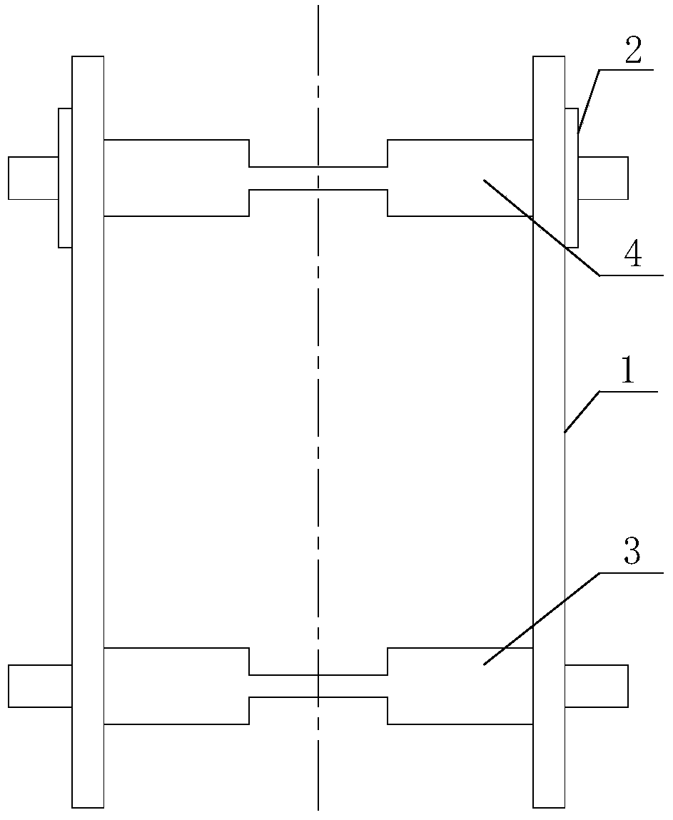
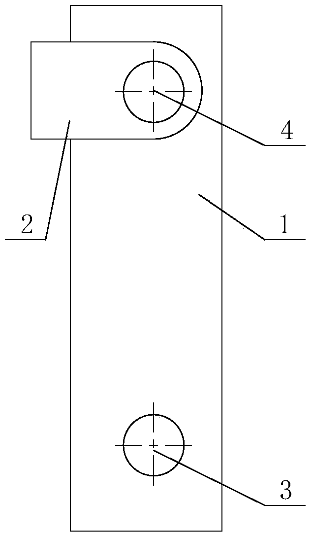
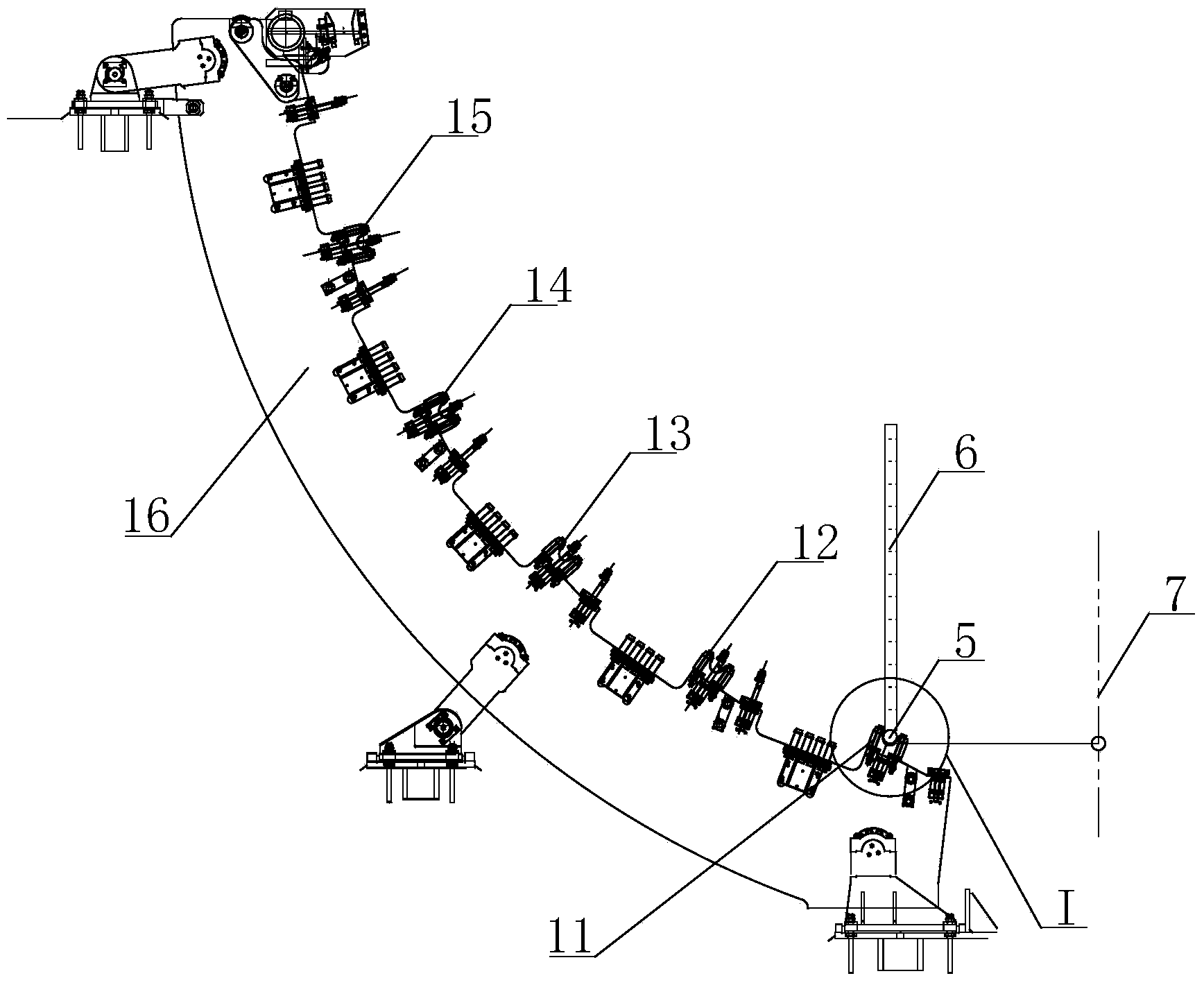
[0039] See Figure 1-Figure 6 , firstly take the 5# positioning U-shaped seat 11 of the arc segment 16 (the last arc segment) as the starting point, and adjust the gaskets in the two directions of the U-shaped seat 11a and b by adjusting 5# according to the measured deviation data , so that its deviation is within the allowable deviation range (make sure that the deviation is in the same direction when adjusting).

[0040]Based on the 5# positioning U-shaped seat 11 of the sector 16, adjust the 4# positioning U-shaped seat 12, and then adjust the 3# positioning U-shaped seat 13 based on the 4# positioning U-shaped seat 12, and so on. The positioning U-shaped seat of 16 has been adjusted. The specific adjustment method takes 5# positioning U-shaped seat 11 as a reference to adjust 5# positioning U-shaped seat 11 as an example: put two false shafts: false shaft 1 5 and false shaft 2 9 on 5# and 4# positioning U-shaped In the seat 12, use the N3 level to measure the elevation o...


PUM


Abstract

The invention relates to a method and a device for inspection measurement of a fan-shaped section base of a continuous casting machine. The method comprises the following steps of putting a false axis into a U-shaped base for positioning, measuring arc fan-shaped sections and straight fan-shaped sections by measuring parameters such as false axis elevation, and measuring the fan-shaped section base by the device, wherein in the measurement, error compensation is carried out. The device can simulate the fan-shaped sections. The method is easy, is convenient for operation, realizes accurate and fast measurement, and shortens a construction period. According to the method, in positioning U-shaped base 5 measurement adjustment of the first arc fan-shaped section, a reference-point casting machine tangent point line is needed; and in positioning U-shaped base measurement adjustment of other fan-shaped sections, only an inside micrometer, a level instrument and an indium steel rule are needed so that the reference-point casting machine tangent point line use is avoided in the positioning U-shaped base measurement adjustment of other fan-shaped sections.

Description

technical field [0001] The invention relates to a measurement technology of large-scale equipment, in particular to a method and device for overhauling and measuring the sector base of a continuous casting machine. Background technique [0002] The steelmaking plants of iron and steel companies have generally adopted the continuous casting technology of continuous casting machines. The sector section is the core equipment of the continuous casting machine. The accuracy of its arc alignment will directly affect the production efficiency of the continuous casting machine. The slab Plate type and quality, etc., while the installation accuracy of the sector base is the basis for the arc alignment of the sector. During the production process of the continuous casting machine, the segment base is affected by many factors such as uneven settlement of the equipment foundation, high temperature environment, dynamic load, etc. After a certain period of production, the arc accuracy of ...

Claims


Application Information

Patent Timeline
Patent Type & Authority Applications(China)
IPC IPC(8): G01C5/00G01B5/14
Inventor 王宏孙秀霞
Owner CHINA THIRD METALLURGICAL GRP
Why Eureka
Try Eureka