
Measuring equipment and measuring method for heat conductivity coefficients of solid materials

A technology of thermal conductivity and solid material, applied in the field of heat and mass transfer, can solve the problems of cumbersome measurement process, large amount of calculation, heat flow loss, etc., to achieve the effect of simple working principle, improved accuracy and improved service life

Inactive Publication Date: 2013-11-27
UNIV OF ELECTRONICS SCI & TECH OF CHINA
View PDF9 Cites 34 Cited by
  • Summary
  • Abstract
  • Description
  • Claims
  • Application Information

AI Technical Summary

Problems solved by technology

[0017] (2) After a stable temperature difference is formed between the hot surface and the cold surface of the sample to be tested, the heat flow flows from the hot surface to the cold surface and is taken away by the cooling water in the radiator. The heat absorbed by the cooling water per unit time that is The measurement device of this method is not easy to simplify, and the measurement process is relatively cumbersome, which is easy to cause heat flow loss;
[0018] (3) Let the cold surface of the sample to be tested be in contact with a cooling plate with known mass and specific heat capacity. When the temperature of the device is stable, measure the heat dissipation rate of the cooling plate to obtain However, it is difficult to solve the heat dissipation rate, and the calculation amount is large

Method used


Image

  • Measuring equipment and measuring method for heat conductivity coefficients of solid materials
  • Measuring equipment and measuring method for heat conductivity coefficients of solid materials
  • Measuring equipment and measuring method for heat conductivity coefficients of solid materials

Examples


Embodiment Construction

[0057] In order to make the object, technical solution and advantages of the present invention clearer, the present invention will be further described in detail below in conjunction with the accompanying drawings and embodiments. It should be understood that the specific embodiments described here are only used to explain the present invention, not to limit the present invention.

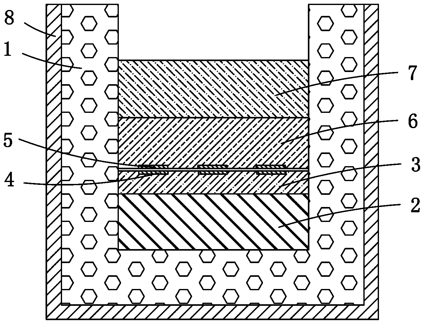
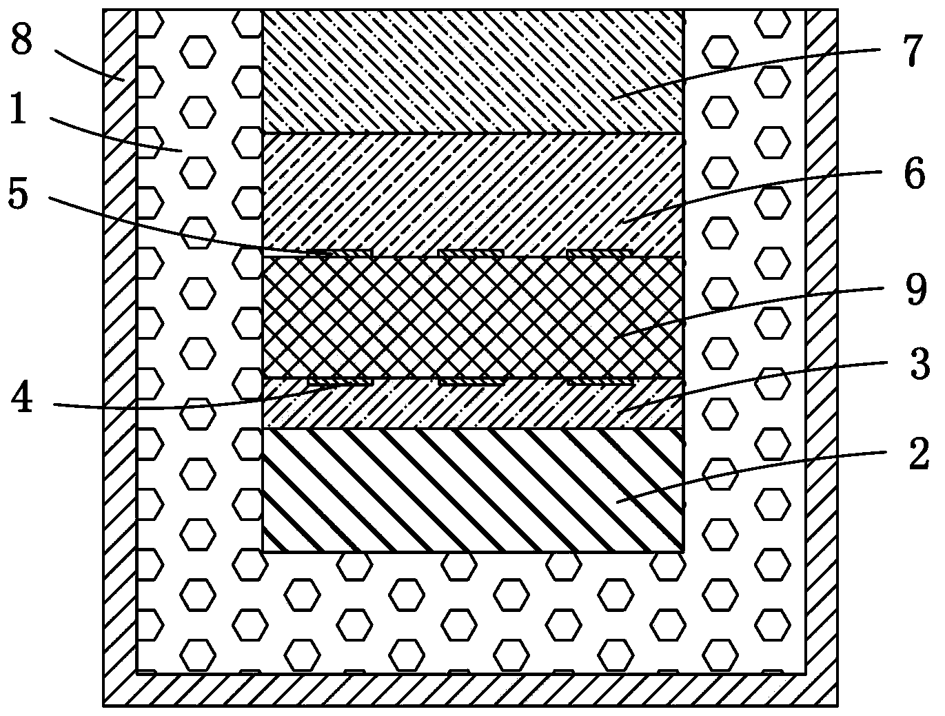
[0058] like figure 1 As shown, the solid material thermal conductivity measurement device in this embodiment includes a heat insulation layer 1 and a heating plate 2, a soaking plate 3, and a temperature sensor group 4 located inside the heat insulation layer 1 and arranged in sequence from bottom to top. , temperature sensor group 5, cooling plate 6 and constant temperature plate 7, the use of heat insulation layer 1 ensures the one-dimensional heat transfer of the sample to be tested from bottom to top during measurement, and the use of vapor chamber and constant temperature plate makes the test ...


PUM


Abstract

The invention discloses measuring equipment for heat conductivity coefficients of solid materials. The measuring equipment comprises a thermal insulating layer (1), and a heating plate (2), a soaking plate (3), a temperature sensor group (4), a temperature sensor group (5), a heat dissipation plate (6) and a constant temperature plate (7) which are arranged inside the thermal insulating layer (1) from bottom up in sequence, wherein two wholes are formed by bonding the heating plate (2) with the soaking plate (3), the heat dissipation plate (6) and the constant temperature plate (7) through heat-conducting silicone grease; the temperature sensor group (4) is mounted on the upper surface of the soaking plate (3) and distributed uniformly on the upper surface of the soaking plate (3); the temperature sensor group (5) is mounted on the lower surface of the heat dissipation plate (6) and distributed uniformly on the lower surface of the heat dissipation plate (6); the measuring equipment further comprises fitting function, which relates to the temperature of the lower surface of the heat dissipation plate (6), of temperature gradient of the lower surface of the heat dissipation plate (6). The invention further discloses a measuring method of the measuring equipment. The measuring equipment and the measuring method can rapidly and accurately measure the heat conductivity coefficients of to-be-measured samples.

Description

technical field [0001] The invention belongs to the technical field of heat and mass transfer, and in particular relates to a device suitable for measuring thermal conductivity of solid materials and a measuring method thereof. Background technique [0002] Thermal conductivity is the proportional coefficient in Fourier's law of thermal conductivity. It is one of the most important thermophysical parameters of a substance. Its size reflects the thermal conductivity of a substance. It is widely used in the fields of chemical industry, energy, materials, power and refrigeration. A crucial piece of data in many industrial processes and product designs, therefore, it is of great practical significance to accurately measure the thermal conductivity of substances under different conditions. The size of the thermal conductivity depends on many factors such as the type, structure, state, temperature and pressure of the substance, so it is very difficult to calculate it accurately. ...

Claims


Application Information

Patent Timeline
IPC IPC(8): G01N25/20
Inventor 郝晓红武宗祥谌雪峰方璐
Owner UNIV OF ELECTRONICS SCI & TECH OF CHINA
Learn More