Overcurrent detection circuit

An overcurrent detection and circuit technology, applied in the direction of measuring electrical variables, measuring current/voltage, measuring devices, etc., can solve problems such as bandwidth limitation and difficulty in achieving fast response, and achieve the effect of avoiding misjudgment and improving response speed

Active Publication Date: 2013-11-27
ELECTRIC POWER RES INST OF GUANGDONG POWER GRID +1
View PDF4 Cites 6 Cited by
  • Summary
  • Abstract
  • Description
  • Claims
  • Application Information

AI Technical Summary

Problems solved by technology

[0005] First, since the above-mentioned overcurrent detection circuit uses the operational amplifier U1 to amplify the current signal, the operating current signal of the system changes rapidly, for example, when the operating current rises rapidly due to a short circuit, the above-mentioned detection circuit is limited by the bandwidth of the operational amplifier U1, Difficulty in responding quickly;

Method used


Image

  • Overcurrent detection circuit
  • Overcurrent detection circuit

Examples


Embodiment 1

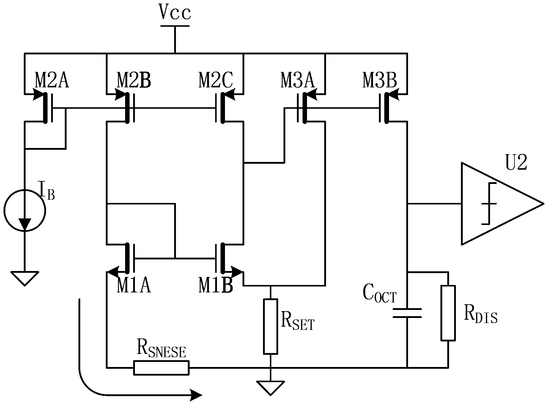
[0023] like figure 2 As shown, the overcurrent detection circuit of Embodiment 1 of the present invention includes a current detection resistor R for sampling the operating current of the system under test SENSE , a voltage comparator U2 with an overcurrent threshold, a current source I B , voltage source Vcc, overcurrent threshold setting resistor R SET , delay capacitor C OCT , the bleeder resistor R DIS , the first N-type MOS transistor M2A, and the second N-type MOS transistor M2B, the third N-type MOS transistor M2C, the fourth N-type MOS transistor M3A, the fifth N-type MOS transistor M3B, the first P Type MOS transistor M1A and the second P-type MOS transistor M1B, wherein, the first P-type MOS transistor M1A and the second P-type MOS transistor M1B are paired, the first N-type MOS transistor M2A, the second N-type MOS transistor M2B and the third The N-type MOS transistor M2C is paired, the fourth N-type MOS transistor M3A is paired with the fifth N-type MOS trans...

Embodiment 2

[0031] Embodiment 2 of the present invention is basically the same as Embodiment 1, and their difference is that in practical applications, taking into account the differences in the tested system, such as standby current, device value and other factors, this Embodiment 2 can be based on a specific proportional relationship The MOS tubes replace the above paired MOS tubes, that is: the first P-type MOS tube M1A and the second P-type MOS tube M1B are proportional MOS tubes, the first N-type MOS tube M2A, the second N-type MOS tube M2B and The third N-type MOS transistor M2C is a proportional MOS transistor, the fourth N-type MOS transistor M3A and the fifth N-type MOS transistor M3B are proportional MOS transistors, that is, any channel of a proportional MOS transistor The lengths are consistent and the channel widths are proportional, wherein the ratio of the second N-type MOS transistor M2B to the third N-type MOS transistor M2C is equal to the ratio of the first P-type MOS tr...

Embodiment 3

[0033] Embodiment 3 of the present invention is that on the basis of Embodiment 1 or Embodiment 2, at least one voltage comparator U2 is added, and the input terminals of each voltage comparator U2 are respectively connected to the fifth N-type MOS transistor M3B and the delay capacitor C OCT connection point, and the overcurrent threshold of each voltage comparator U2 is incremented. Because of the delay capacitor C in the present invention OCT The delay time generated on is inversely proportional to the overcurrent current of the system under test, that is, the capacitance C OCT The delay time generated on the above can be adaptive to the overcurrent current of the system under test. Therefore, the present invention does not need to set different delay times on each voltage comparator as in the prior art, thereby realizing continuous control and improving the overcurrent The detection reliability of the detection circuit reduces the debugging cost of the overcurrent detecti...


PUM


Abstract

The invention discloses an overcurrent detection circuit. The overcurrent detection circuit includes a detecting resistor (RSENSE) for sampling a working current of a system under test, and a voltage comparator which is provided with an overcurrent threshold value (U2); the overcurrent detection circuit is characterized by further comprising a current source (IB), a voltage source (Vcc), an overcurrent threshold value setting resistor (RSET), a delay capacitor (COCT), a discharge resistor (RDIS), a first N-type MOS tube (M2A), a second N-type MOS tube (M2B) and a third N-type MOS tube (M2C) which form a current mirror, a fourth N-type MOS tube (M3A) and a fifth N-type MOS tube (M3B) which form another current mirror, a first P-type MOS tube (M1A) and a second P-type MOS tube (M1B) which form still another current mirror. The overcurrent detection circuit of the invention improves the overcurrent fault response speed of the system under detection and test.

Description

technical field [0001] The invention relates to an overcurrent detection circuit, which is mainly used in the fields of battery management systems and motor control systems, and plays a role in detecting the occurrence of overcurrent in the system due to short circuit and overload. Background technique [0002] Usually, the overcurrent detection circuit is used to detect the system overcurrent fault caused by short circuit, overload and other reasons in the battery management, motor control and other systems, so as to cut off the system circuit in time and avoid serious consequences such as overheating and burning of the system. [0003] like figure 1 As shown, the over-current detection circuit in the prior art is often implemented using an operational amplifier circuit, which includes a current-sensing resistor R SENSE , an amplifying circuit composed of operational amplifier U1 and resistors R1 to R4, and a voltage comparator U2, where the current-sense resistor R SENSE...

Claims


Application Information

Patent Timeline
Patent Type & Authority Applications(China)
IPC IPC(8): G01R19/165
Inventor 孙卫明赵伟张永旺罗敏赵建华
Owner ELECTRIC POWER RES INST OF GUANGDONG POWER GRID
Why Eureka
Try Eureka