Manufacturing method of isolation type COB light source module

A technology of light source module and manufacturing method, which is applied to electrical components, circuits, semiconductor devices, etc., can solve problems such as energy loss, poor heat sink, and reduce the quantum efficiency of phosphors, so as to prolong the service life and optimize the optical quality.

Inactive Publication Date: 2013-11-27
GUANGZHOU LEDTEEN OPTOELECTRONICS CO LTD
View PDF5 Cites 14 Cited by
  • Summary
  • Abstract
  • Description
  • Claims
  • Application Information

AI Technical Summary

Problems solved by technology

The LED chip is in direct contact with the phosphor powder. Since the LED chip itself is a heating element, the phosphor powder will be affected by heat during long-term use, resulting in serious light decay, which affects the quality of the LED.
In addition, during the use of the LED chip, the phosphor powder excited by the blue light will cause energy loss, and then generate heat. This heat and the heat generated by the LED chip will accumulate in the silica gel layer of the phosphor powder. The temperature of the silicone layer can be as high as 220°C, which will greatly affect the life and quality of the LED chip
This thermal effect reduces the quantum efficiency of the phosphor, which in turn affects the overall luminous efficiency
In addition, air remains in the phosphor silica gel layer produced by the traditional COB light source module manufacturing method, resulting in multiple air bubbles in the phosphor silica gel layer, which affects the optical quality of the COB light source

Method used


Image

  • Manufacturing method of isolation type COB light source module
  • Manufacturing method of isolation type COB light source module

Examples


Embodiment Construction

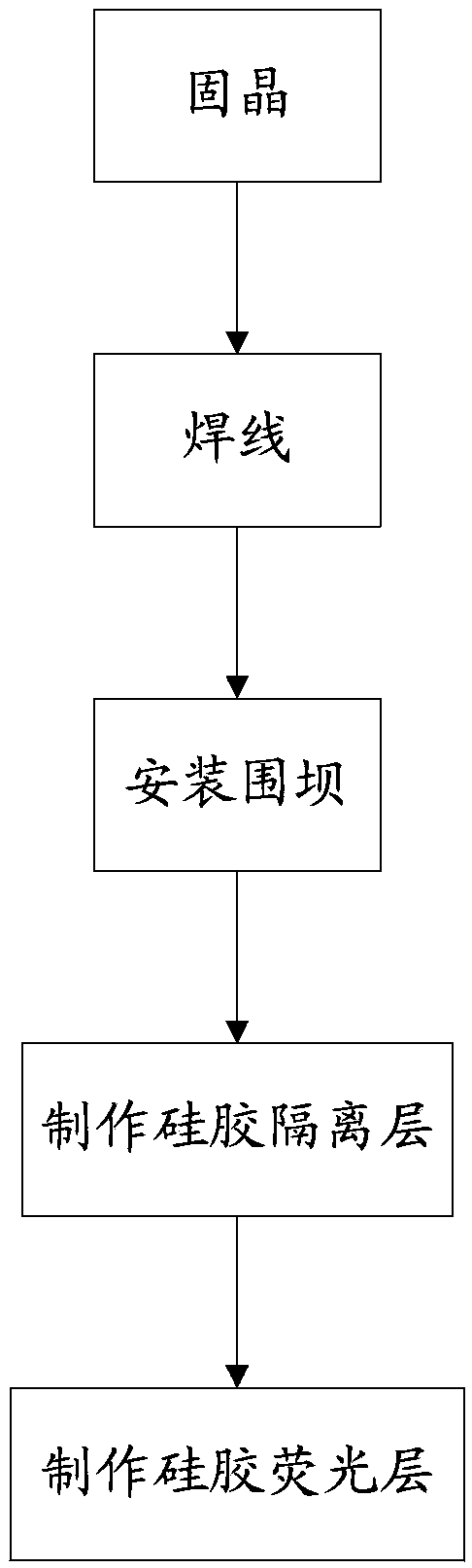
[0036] Below in conjunction with accompanying drawing and specific embodiment, the present invention will be further described:

[0037] See figure 1 , the present invention relates to a manufacturing method of an isolated COB light source module, and its preferred implementation includes the following steps:

[0038] Die-bonding step: apply liquid crystal-bonding glue on the crystal-bonding position of the substrate, mount the LED chip on the crystal-bonding position, and bake the substrate to solidify the crystal-bonding glue, so that the LED chip can be fixed on the crystal-bonding position On the surface, it has better adhesion.

[0039] The above-mentioned solid crystal step includes the following sub-steps:

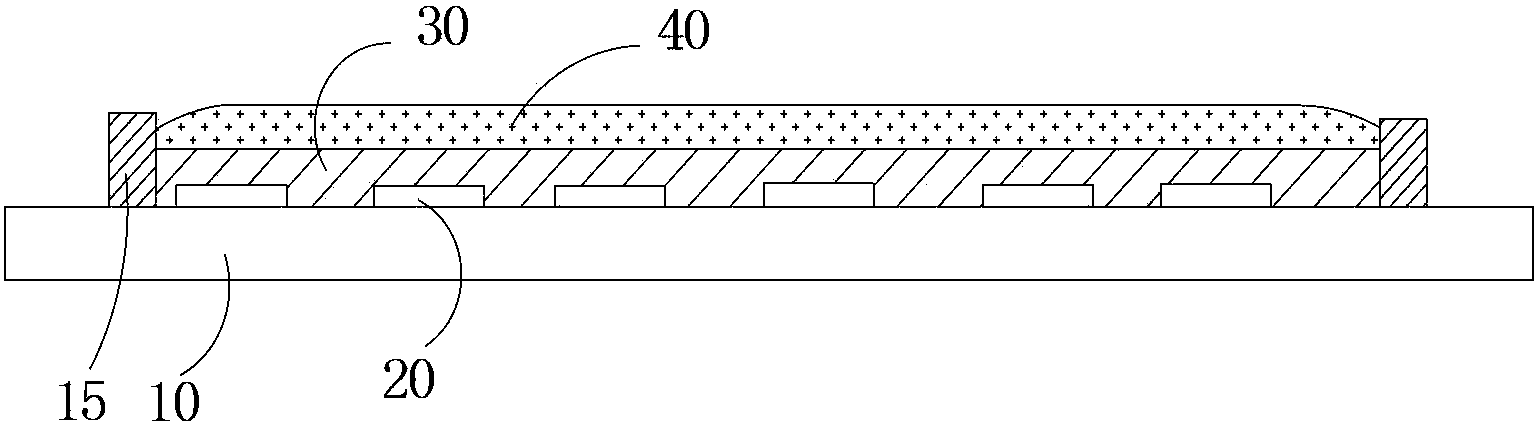
[0040] Wherein, the base plate is provided with several evenly distributed crystal bonding positions, each crystal bonding position includes a mounting plate, a positive electrode pad and a negative electrode bonding pad, and the mounting plate is located between ...


PUM


Abstract

The invention discloses a manufacturing method of an isolation type COB light source module. The manufacturing method of the isolation type COB light source module comprises the steps of crystal fixing, namely a crystal fixing position on a substrate is coated with liquid crystal fixing glue, an LED chip is attached to the crystal fixing position, and then the substrate is roasted; wire welding, namely one end of a gold wire is welded on a welding disc of the crystal fixing position, and the other end of the gold wire is welded on the electrode of the LED chip; surrounding dam installing, namely organic silica gel is dispersed on the substrate to form an annular surrounding dam; silica gel isolating layer manufacturing, namely liquid silica gel is dropped in the surrounding dam, and the substrate is roasted to enable the liquid silica gel to be solidified to form a silica gel isolating layer; silica gel fluorescent layer manufacturing, namely fluorescent powder and the liquid silica gel are evenly mixed to obtain liquid fluorescent silica gel, the liquid fluorescent silica gel is dropped onto the silica gel isolating layer, and the substrate is roasted to enable the liquid fluorescent silica gel to be solidified to form a silica gel fluorescent layer. The manufacturing method of the isolation type COB light source module has the advantages that the service life of the LED chip can be prolonged and light emitting quality can be optimized.

Description

[0001] technical field [0002] The invention relates to a manufacturing method of an isolated COB light source module. [0003] Background technique [0004] The COB light source produced by the traditional COB light source module production method generally includes a plurality of blue LED chips, and the LED chips are covered with a yellow phosphor silica gel layer. The blue light emitted by the blue LED chip excites the yellow phosphor to emit yellow-green light, and the yellow-green light is mixed with the blue light emitted by the blue LED chip to form white light. The LED chip is in direct contact with the phosphor powder. Since the LED chip itself is a heat generating body during use, the phosphor powder is affected by heat during long-term use, resulting in serious light attenuation, thereby affecting the quality of the LED. In addition, during the use of the LED chip, the phosphor powder excited by the blue light will cause energy loss, and then generate heat. Thi...

Claims


Application Information

Patent Timeline
Patent Type & Authority Applications(China)
IPC IPC(8): H01L33/48H01L33/52
Inventor 陈志威高艳春夏雪松
Owner GUANGZHOU LEDTEEN OPTOELECTRONICS CO LTD
Why Eureka
Try Eureka