Multi-input boost converter based on Switch-Capacitor networks

A boost converter, multi-input technology, applied in the direction of conversion equipment without intermediate conversion to AC, can solve the problems of insufficient boost capacity and low component utilization, and achieve strong boost capacity and component utilization High, small capacitive voltage stress effect

Inactive Publication Date: 2013-11-27
CHONGQING UNIV
View PDF2 Cites 3 Cited by
  • Summary
  • Abstract
  • Description
  • Claims
  • Application Information

AI Technical Summary

Problems solved by technology

However, the existing multi-input DC converters have the serious disadvantages of low component utilization during time-sharing power supply and insufficient boosting capacity in high boosting applications.

Method used


Image

  • Multi-input boost converter based on Switch-Capacitor networks
  • Multi-input boost converter based on Switch-Capacitor networks
  • Multi-input boost converter based on Switch-Capacitor networks

Examples


Embodiment 1

[0024] Embodiment 1, multi-input boost converter based on Switch-Capacitor network

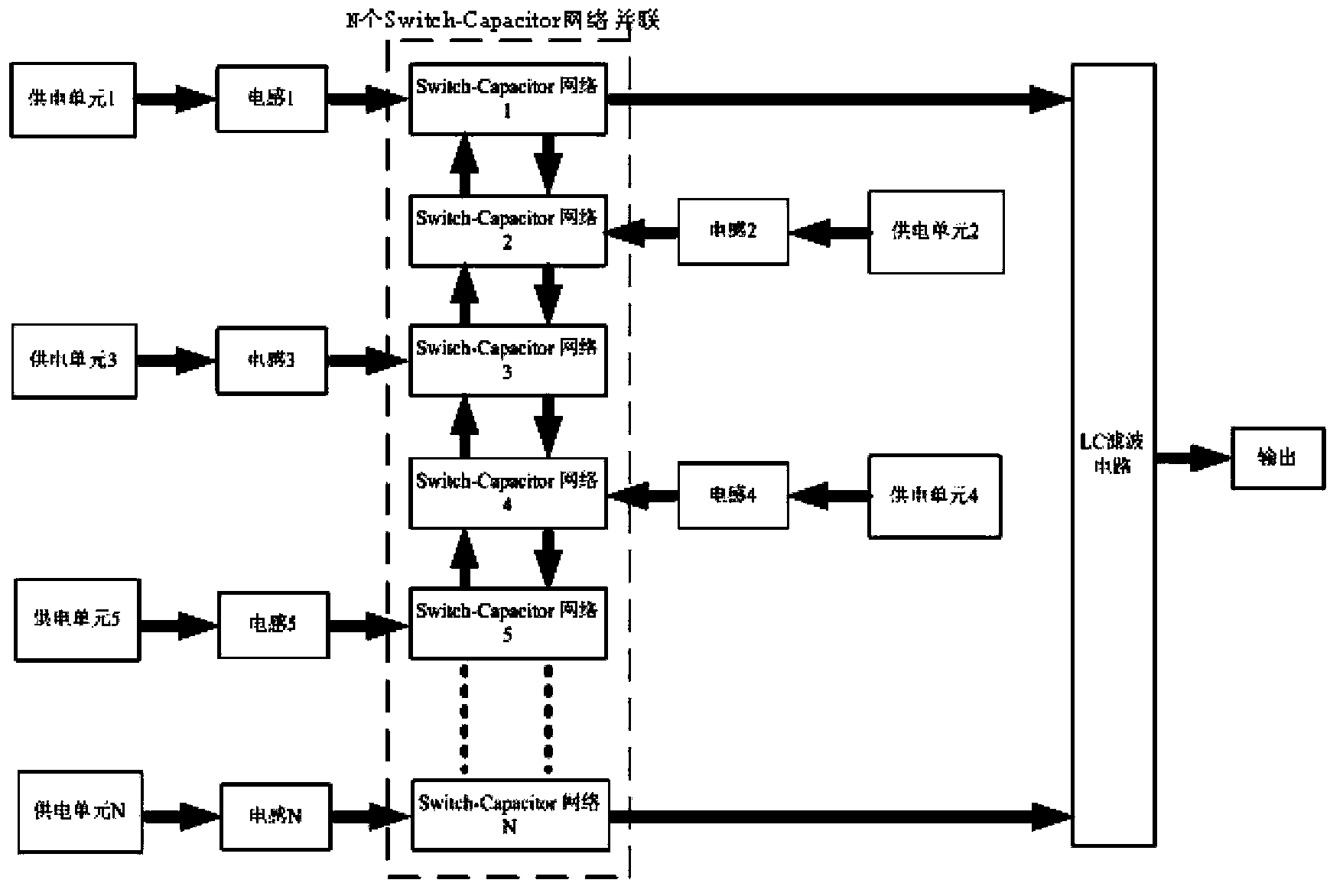
[0025] The circuit structure of the new energy combined power supply system based on the multi-input boost converter based on the Switch-Capacitor network is as follows: figure 2 shown. Any input voltage is boosted through the parallel accumulation of multiple Switch-Capacitor networks, and then through the LC filter circuit to achieve an output voltage with smaller ripples. The input source is connected to any Switch-Capacitor network, and its input voltage will achieve the same output voltage through the accumulation of all network capacitor voltages, that is, each network contributes a part of the voltage to the output terminal, which is the multi-input boost converter. uniqueness. Therefore, compared with the existing multi-input converter, the multi-input boost converter greatly improves the utilization rate of components.

[0026] Depending on the number of Switch-Capacitor networks ...

Embodiment 2

[0037] Embodiment 2, taking power supply unit 1 as an example (power supply unit 1 chooses any one of photovoltaic power supply unit, fuel cell power supply unit and wind energy power supply unit)

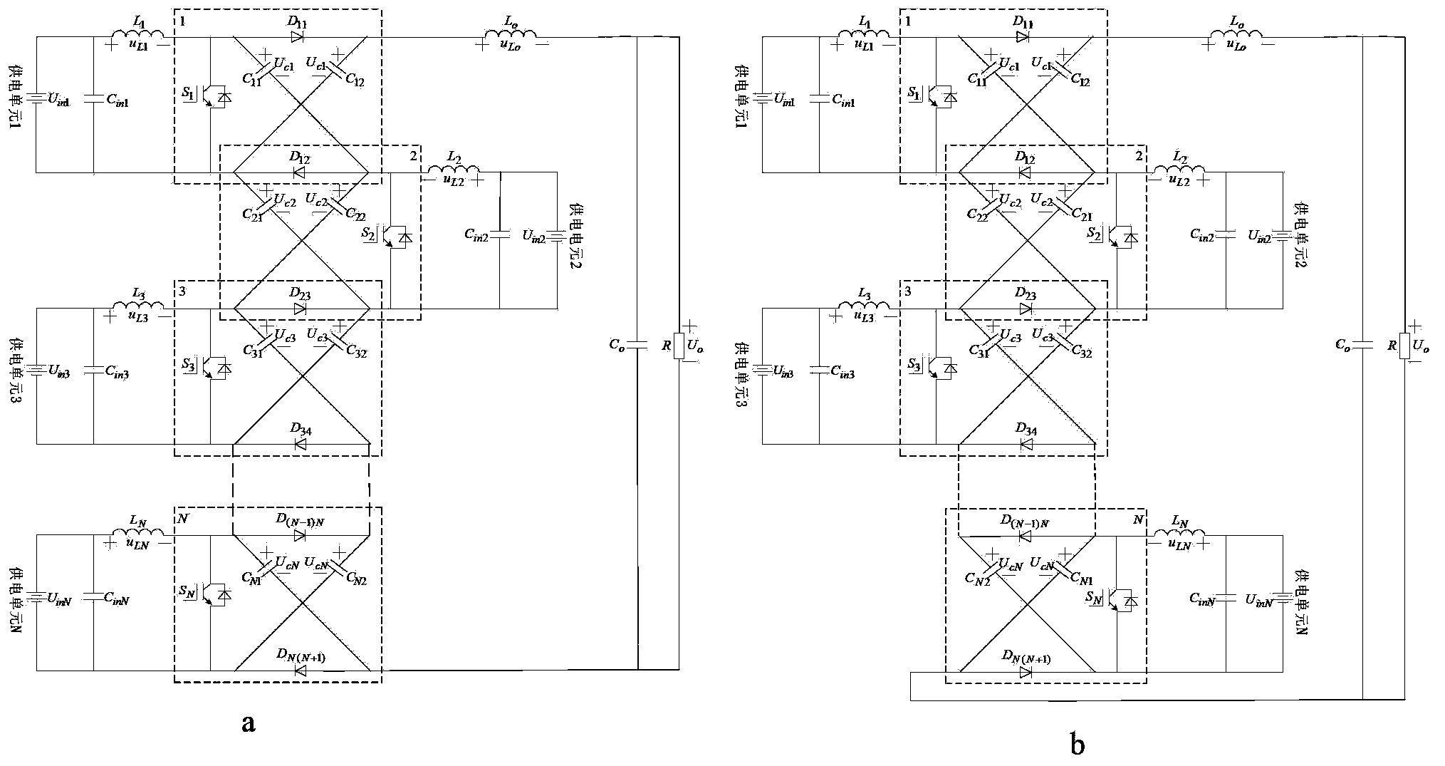
[0038] In the new energy joint power supply system, when only the power supply unit 1 supplies power, the circuit topology of the three-input boost converter is as follows Figure 5 As shown, the equivalent circuit is as Figure 6 as shown, Figure 6 (a) is the switch on, (b) is the switch off. The three-input boost converter obtains a higher output voltage through accumulative boosting of capacitor voltages in three Switch-Capacitor networks.

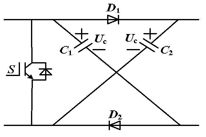
[0039] When the three switches S 1 , S 2 , S 3 While conducting, the diode D 11 、D 12 、D 23 、D 34 are turned off, the equivalent circuit such as Figure 6 (a) shown. At this point, the capacitor C in network 1 11 with C 12 , the capacitor C in network 2 21 with C 22 and capacitor C in network 3 31 with C 32 respectively int...

Embodiment 3

[0047] Embodiment 3, taking the power supply unit 2 as an example (the power supply unit 2 chooses any one of photovoltaic power supply unit, fuel cell power supply unit and wind energy power supply unit)

[0048] When only the power supply unit 2 supplies power, the circuit topology of the three-input boost converter is as follows Figure 7 As shown, the equivalent circuit is as Figure 8 as shown, Figure 8 (a) is the switch on, (b) is the switch off. In this case, the working principle of the three-input boost converter is the same as when only the power supply unit 1 supplies power, and the voltages of the capacitors in the three Switch-Capacitor networks are accumulated and boosted to obtain a higher output voltage.

[0049] When the three switches S 1 , S 2 , S 3 When turned on simultaneously, the equivalent circuit such as Figure 8 (a) shown. At this time, the inductance L 2 and inductance L o The magnitudes of the voltages on are:

[0050] u L2 =U in2 ...


PUM


Abstract

The invention discloses a multi-input boost converter based on Switch-Capacitor networks. The multi-input boost converter is mainly formed by connecting multiple Switch-Capacitor networks in parallel, the capacitor voltages in all the Switch-Capacitor networks are equal, and a larger output voltage is achieved through the mode of accumulating multiple network capacitor voltages. The multi-input boost converter is used for replacing multiple single-input boost converters. The multi-input boost converter allows the input of multiple energy sources, the properties, the amplitude values and the characters of input sources can be identical and can also be very different, the input sources can supply power to loads respectively or simultaneously, and therefore the stability and the flexibility of a system are improved, the preferential utilization of the energy sources is achieved, and system cost is lowered.

Description

technical field [0001] The invention relates to the field of power electronics, in particular to a multi-input boost converter based on a Switch-Capacitor network. Background technique [0002] As a non-renewable energy source, fossil energy is being exhausted day by day, and the environmental pollution caused by it is becoming more and more serious. Renewable energy has the characteristics of cheap, reliable, clean and pollution-free, and abundant energy, so renewable energy power generation has shown a good market prospect. At present, the most widely used forms of renewable energy power generation include photovoltaic power generation, wind power generation, fuel cell power generation, hydropower generation, geothermal power generation, etc., but all have shortcomings such as unstable power supply, discontinuity, and changes with climate conditions. Therefore, it is necessary to A distributed power supply system that uses multiple energy sources for joint power supply. ...

Claims


Application Information

Patent Timeline
Patent Type & Authority Applications(China)
IPC IPC(8): H02M3/10
Inventor 侯世英陈剑飞孙韬邹学伟张立帅陈复梁涛龚嫄毕晓辉朱传亮
Owner CHONGQING UNIV
Why Eureka
Try Eureka