Fixed-frequency constant on-off time control method of dynamic voltage regulating switch converter

A dynamic voltage regulation, switching converter technology, applied in the direction of regulating electrical variables, control/regulating systems, converting DC power input to DC power output, etc., can solve problems such as switching frequency changes, difficulty in designing output filters, etc. Effects of small output voltage ripple, small voltage overshoot, and small voltage sag

Inactive Publication Date: 2013-11-27
SOUTHWEST JIAOTONG UNIV
View PDF2 Cites 13 Cited by
  • Summary
  • Abstract
  • Description
  • Claims
  • Application Information

AI Technical Summary

Problems solved by technology

The advantage of this control is that there is no error amplifier, and its transient response speed is relatively fast; however, when the input voltage and output reference voltage of this control change, the switching frequency will change greatly, making it difficult to design the output filter

Method used


Image

  • Fixed-frequency constant on-off time control method of dynamic voltage regulating switch converter
  • Fixed-frequency constant on-off time control method of dynamic voltage regulating switch converter
  • Fixed-frequency constant on-off time control method of dynamic voltage regulating switch converter

Examples


Embodiment 1

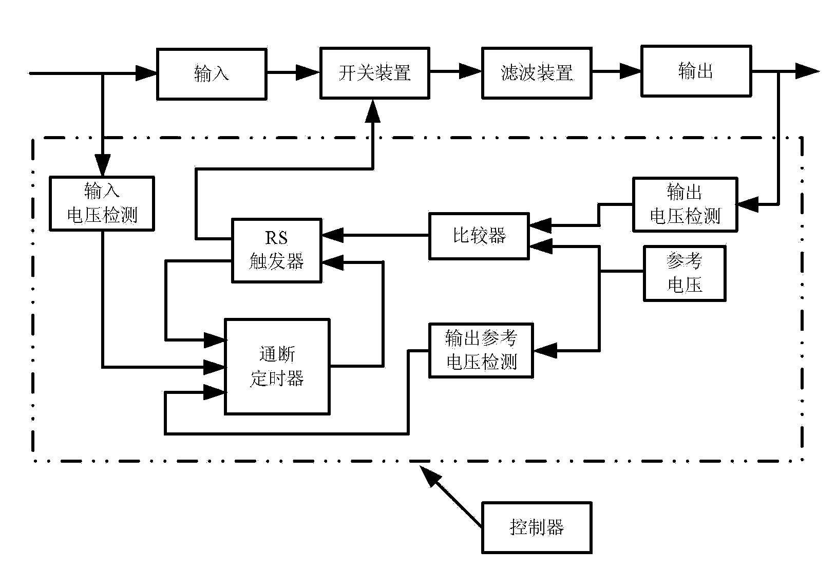
[0037] figure 1As shown, the specific implementation of the present invention is: a dynamic voltage regulation switching converter constant frequency constant on-off time control device, a dynamic voltage regulation switching converter constant frequency constant on-off time control technology device, the controller is mainly composed of input voltage It consists of a detection device, an output voltage detection device, an output reference voltage detection device, a comparator, a trigger, an on-off timer, and a drive circuit. The output voltage is compared with the reference voltage by the detection device to generate a comparison signal; after the input voltage and output reference voltage are detected, they act together with the RS trigger on the on-off timer to generate a timing signal; the comparison signal and the timing signal act together on the RS trigger The output of the RS flip-flop is used to control the switching device of the converter after passing through th...

Embodiment 2

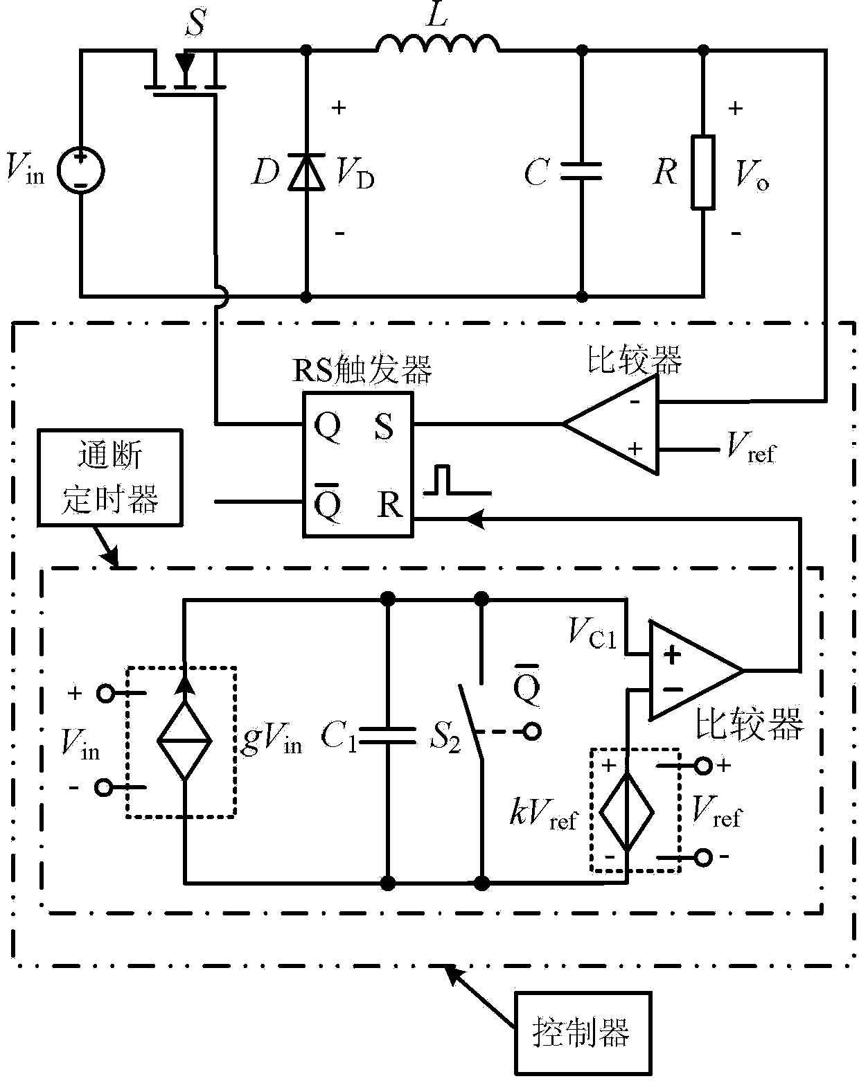
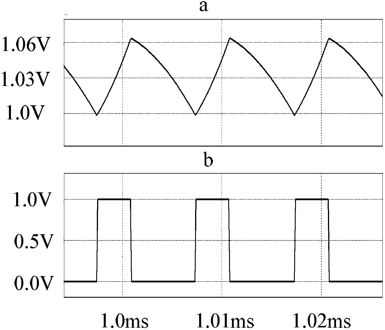
[0052] Figure 11 It shows that, compared with Embodiment 1, the power converter of this example is a Boost converter, and the technical solution ① constant on-time mode is adopted, and the control device is roughly the same as that of Embodiment 1. At this time, the controlled current of the on-off timer The source input signal is the output reference voltage, and the controlled voltage source input signal is the difference between the output reference voltage and the input voltage. It is also proved by simulation that the output voltage of the present invention is stable, the dynamic response speed is fast, and the switching frequency is constant.

[0053] In addition to controlling the Buck converter and Boost converter in the above embodiments, the present invention can also be used in switching power supplies composed of power circuits such as Buck-Boost converters.


PUM


Abstract

The invention discloses a fixed-frequency constant on-off time control method of a dynamic voltage regulating switch converter and a device thereof. According to an output voltage and an output voltage reference, a comparison signal is generated, and is combined with a timing signal generated by an on-off timer so as to control an RS trigger; the RS trigger produces a control signal to control a switch converter; the arranged on-off timer is controlled by an input voltage and the output reference voltage, so that on-off time of the on-off timer automatically changes with the input voltage and the output reference voltage; and a switch frequency maintains constant. According to the invention, the advantages of fast transient response speed and good stability, and the advantage that the switch frequency does not change with the input voltage, the output reference voltage, and the load current are realized.

Description

technical field [0001] The invention relates to switching power supply equipment, especially the constant frequency and constant on-off time control technology of a dynamic voltage regulation switching converter and its realization device. Background technique [0002] With the rapid development of power electronics technology, the relationship between power electronic equipment and people's work and life is becoming increasingly close, and electronic equipment is inseparable from a reliable power supply. Due to the advantages of small size, high efficiency and light weight, switching power supply has replaced linear power supply in many fields. Switching power supply technology has become the most active branch in the field of power electronics, and has attracted great attention from power supply technology researchers. With the rapid development of science and technology, the functions of electronic products are becoming more and more powerful, and their demand for power s...

Claims


Application Information

Patent Timeline
Patent Type & Authority Applications(China)
IPC IPC(8): H02M3/156H02M1/14
Inventor 许建平徐杨军何圣仲王金平陈利
Owner SOUTHWEST JIAOTONG UNIV
Why Eureka
Try Eureka