Single-incentive rotating ultrasonic motor

An ultrasonic motor, single excitation technology, applied in the directions of generators/motors, electrical components, piezoelectric effect/electrostrictive or magnetostrictive motors, etc. Affect motor torque and speed stability, poor motor torque and speed stability, etc., to achieve the effects of stable vibration performance, high energy conversion efficiency, and large power capacity

Inactive Publication Date: 2013-11-27
SUZHOU UNIV OF SCI & TECH
View PDF7 Cites 10 Cited by
  • Summary
  • Abstract
  • Description
  • Claims
  • Application Information

AI Technical Summary

Problems solved by technology

Although the motor has the advantages of large output torque, the six piezoelectric ceramic sheets of the motor must be staggered and installed by 60 degrees according to the polarization partition, and its structure is complicated. Spiral motion (rotational force) can easily cause misalignment between piezoelectric ceramic sheets, and it is difficult to ensure the technical requirement of 60 degrees of misalignment between adjacent piezoelectric ceramic sheets; in addition, there is no positioning device between the stator and rotor of the motor, which The accuracy of the contact position between the stator and the rotor is affected, which in turn affects the stability of the torque and speed of the motor; therefore, this type of rotating ultrasonic motor has a complex structure and requires high contact position accuracy between the stator and the rotor. Difficult manufacturing and installation, poor stability of motor torque and speed, etc.

Method used


Image

  • Single-incentive rotating ultrasonic motor
  • Single-incentive rotating ultrasonic motor

Examples


Embodiment Construction

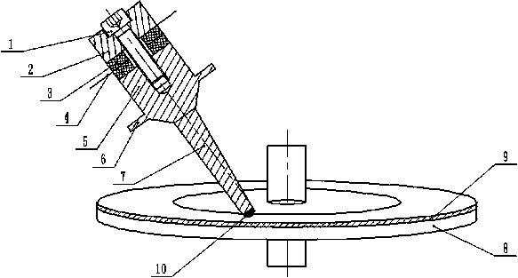
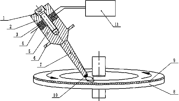
[0016] combine figure 1 , 2 As shown, the single-excitation rotary ultrasonic motor includes a stator and a rotor. The rotor includes a turntable 8 and a friction layer 9 bonded to the surface of the turntable 8; the stator includes an ultrasonic vibration transducer, an elliptical vibration mode converter 6 and a friction drive block 10 ; The outer contour of the ultrasonic vibration transducer is cylindrical, which includes a bolt 1 and a rear cover 2, a piezoelectric ceramic sheet 3, an electrode sheet 4 and a front cover 5 that are sequentially sleeved on the bolt 1, and the front cover 5 A flange 6 that can be connected with other structural devices is provided, and the rear cover 2 and the front cover 5 are connected and pressed by bolts 1 to the rear cover 2, the piezoelectric ceramic sheet 3, the electrode sheet 4 and the front cover 5 , constituting the energy conversion part of the single-excitation rotary ultrasonic motor, which converts the ultrasonic electric ene...


PUM


Abstract

The invention discloses a single-incentive rotating ultrasonic motor. A rotor comprises a rotating disc and a friction layer arranged on the surface of the rotating disc. A stator comprises an ultrasonic vibration transducer, an elliptic vibration mode converter and a friction driving block arranged at the front end of the elliptic vibration mode converter, wherein the elliptic vibration mode converter is arranged at the front end of the ultrasonic vibration transducer and is of an inclined wedge-shaped structure, the elliptic vibration mode converter can convert longitudinal ultrasonic vibration generated by the ultrasonic vibration transducer into longitudinal and bent composite ultrasonic elliptic vibration at the tail end of the elliptic vibration mode converter and on the friction driving block, and the rotor is driven to continuously rotate.

Description

technical field [0001] The invention relates to the field of ultrasonic motors utilizing the inverse piezoelectric effect of piezoelectric ceramics, in particular to a single-excitation rotary ultrasonic motor. Background technique [0002] The rotary ultrasonic motor is a new type of micro-motor developed and applied rapidly in the 1980s. It is an electromechanical coupling device that uses the inverse piezoelectric effect of piezoelectric materials to convert electrical energy to mechanical energy. Through the friction between the stator and the rotor, the The micro-vibration of the elastomer is converted into the macro-rotational motion of the rotor, which directly pushes the load. Because of its small size, light weight, low speed and high torque, low noise, fast response, high positioning accuracy, no electromagnetic interference and strong environmental adaptability, it has been increasingly widely used in medical, aerospace, robotics, MEMS and other technical fields. ...

Claims


Application Information

Patent Timeline
Patent Type & Authority Applications(China)
IPC IPC(8): H02N2/10H02N2/12
Inventor 殷振李华李艳曹自洋刘义生吴永芝陈玉荣任坤张峰吕自强
Owner SUZHOU UNIV OF SCI & TECH
Why Eureka
Try Eureka