Universal automatic testing and fault diagnosis system

A fault diagnosis system and automatic test technology, applied in transmission systems, digital transmission systems, transmission monitoring, etc., can solve problems such as wrong guidance of maintenance personnel, failure to achieve maintenance guarantee, and long-distance faults, etc., and achieve the effect of strong versatility

Active Publication Date: 2013-11-27
华北计算技术研究所
View PDF4 Cites 36 Cited by
  • Summary
  • Abstract
  • Description
  • Claims
  • Application Information

AI Technical Summary

Problems solved by technology

In addition, for the signal test and processing results, most of the fault diagnosis is carried out by manual judgment. The efficiency of this manual diagnosis method is relatively low. rich, the diagnosis res

Method used


Image

  • Universal automatic testing and fault diagnosis system
  • Universal automatic testing and fault diagnosis system
  • Universal automatic testing and fault diagnosis system

Examples


Embodiment 1

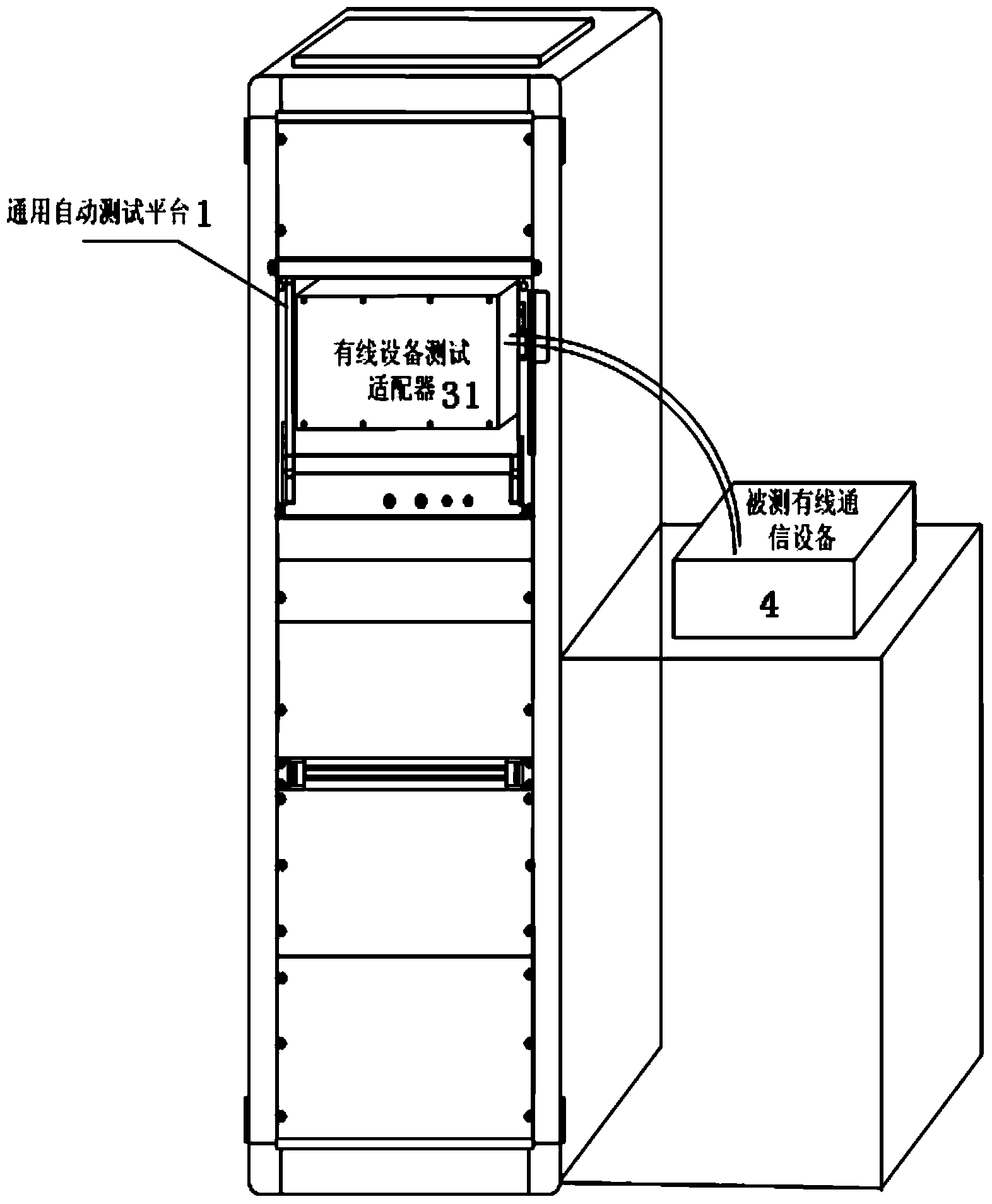
[0033] Embodiment 1: The testing process of the wired equipment is illustrated by the testing method of the multiline transmission equipment:

[0034] Such as Figure 7 As shown, the general automatic test platform 1 is connected to the wired device test adapter 31 through the VPC90 fixture 5, and the device A (communication device under test) and the device B (the intact device) are connected through the double-wired cable, and the voice interface of the device A is connected through the cable Connect with the wired device test adapter's channel 1 interface, the data interface of device A is connected to the data 1 interface of the wired device test adapter 31 through a cable, and the device B's channel interface is connected to the wired device test adapter 31's channel 2 through a cable, The data interface of device B is connected to the data 2 interface of the wired device test adapter 31 through a cable. The test system first initializes the parameters of the general aut...

Embodiment 2

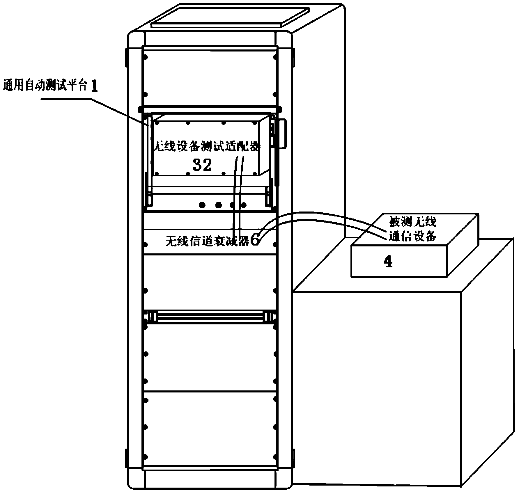
[0035] Embodiment 2: Illustrate the testing process of wireless communication equipment with the ultrashort wave radio station testing method:

[0036] Such as Figure 8As shown, the general automatic test platform 1 is connected with the wireless device test adapter 32 through the VPC90 fixture 5, and the antenna feed port of the ultrashort wave radio station is connected to the A end of the wireless channel attenuator 6 through a cable, and the B end of the wireless channel attenuator 6 is connected to To the radio frequency port 323 of the wireless device test adapter, connect the audio interface of the ultrashort wave radio station to the audio interface 324 of the wireless device test adapter through a cable. Take the carrier power test of the transmitter as an example to illustrate the test process: put the ultrashort wave radio station in the fixed-frequency plain voice mode, and the test system sends control commands to the digital IO module 18 of the general automatic...


PUM


Abstract

The invention relates to a universal automatic testing and fault diagnosis system which is characterized in that a universal automatic testing platform, input-output equipment and an interface adaptor are included, the input-output equipment is connected with the universal automatic testing platform, tested communication equipment is connected the universal automatic testing platform through a corresponding equipment testing adaptor, the universal automatic testing platform comprises a zero-slot controller and testing instruments, the zero-slot controller is provided with a testing system and a fault diagnosis expert system, the testing system is used for carrying out initial setting on the universal automatic testing platform and the interface adaptor during automatic testing and sending testing orders and testing parameters to the testing instruments according to testing needs, the testing instruments transmit corresponding testing signals to the tested communication equipment for testing through the interface adaptor according to the testing orders and the testing parameters, testing result signals of the tested communication equipment are fed back to the testing instruments through the interface adaptor, the testing system collects the signals of the testing instruments and carries out processing and analyzing, if testing results are not qualified, the fault diagnosis expert system carries out intelligent fault diagnosis, and fault is located to the plate level.

Description

technical field [0001] The invention relates to the technical field of automatic testing and fault diagnosis, in particular to a general automatic testing and fault diagnosis system suitable for twelve types of communication equipment. Background technique [0002] There are many types of communication electronic equipment, complex signal types (according to different classification methods can be divided into analog / digital signals, wireless / wired signals, low-frequency / high-frequency signals, voice / image / data signals, etc.), many technical parameters, and accurate testing Accuracy and real-time requirements are relatively high. [0003] Currently widely used communication equipment test and diagnosis systems are usually based on the detection of typical parameters of products, most of which are a set of test equipment for a type of communication equipment. In addition, for the signal test and processing results, most of the fault diagnosis is carried out by manual judgmen...

Claims


Application Information

Patent Timeline
IPC IPC(8): H04B17/00H04L12/26
Inventor 董宝良刘蕊田野项勇李琳琳冯肖珊傅晓曦李江
Owner 华北计算技术研究所
Why Eureka
Try Eureka