
Method for fast configuring remote video monitoring system

A monitoring system and remote video technology, applied in closed-circuit television systems, transmission systems, electrical components, etc., can solve the problems of time-consuming, labor-intensive, cost-increasing, and obstacles to the promotion and application of remote video monitoring systems, and achieve simple setup, high flexibility and Adaptive, simplified deployment effects in the configuration process

Inactive Publication Date: 2013-11-27
INST OF SOFTWARE - CHINESE ACAD OF SCI +1
View PDF4 Cites 54 Cited by
  • Summary
  • Abstract
  • Description
  • Claims
  • Application Information

AI Technical Summary

Problems solved by technology

Since the installation and deployment of remote video surveillance systems involves a large number of steps and links such as equipment installation, network cable laying, network settings, and system debugging, such systems often need to be built by professional construction personnel, which is not only time-consuming and laborious, but also increases additional costs. Therefore, Small and micro enterprises and individual users often do not adopt
At the same time, due to the complexity of re-laying the network and reconfiguring network parameters, and once the surveillance cameras are deployed in the existing remote video surveillance system, even if the monitoring environment changes, it is difficult for users to move or redeploy the surveillance cameras. It also brings obstacles to the further promotion and application of remote video surveillance systems.

Method used


Image

  • Method for fast configuring remote video monitoring system
  • Method for fast configuring remote video monitoring system

Examples


Embodiment Construction

[0026] Below in conjunction with accompanying drawing and specific embodiment the present invention is described in further detail:

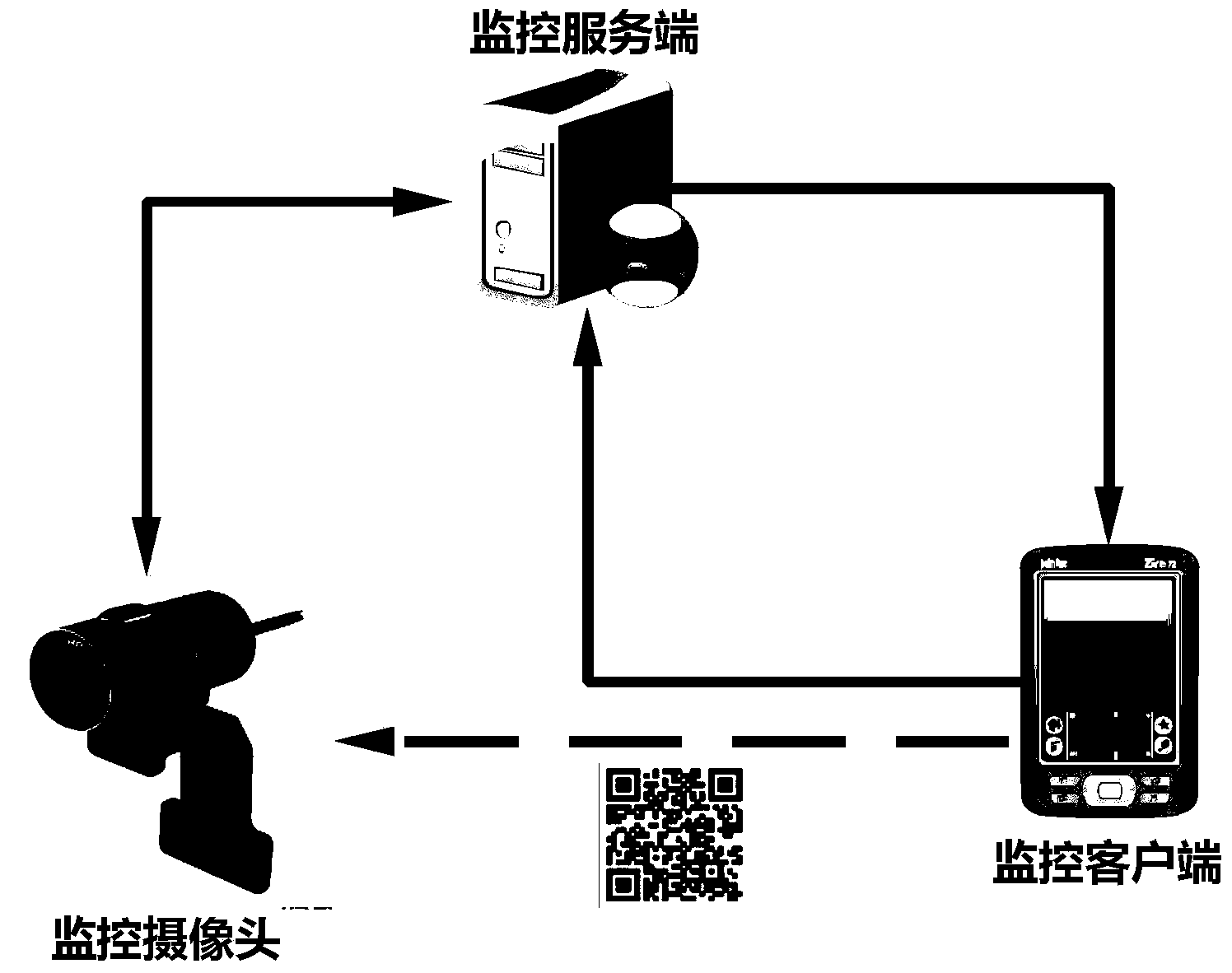
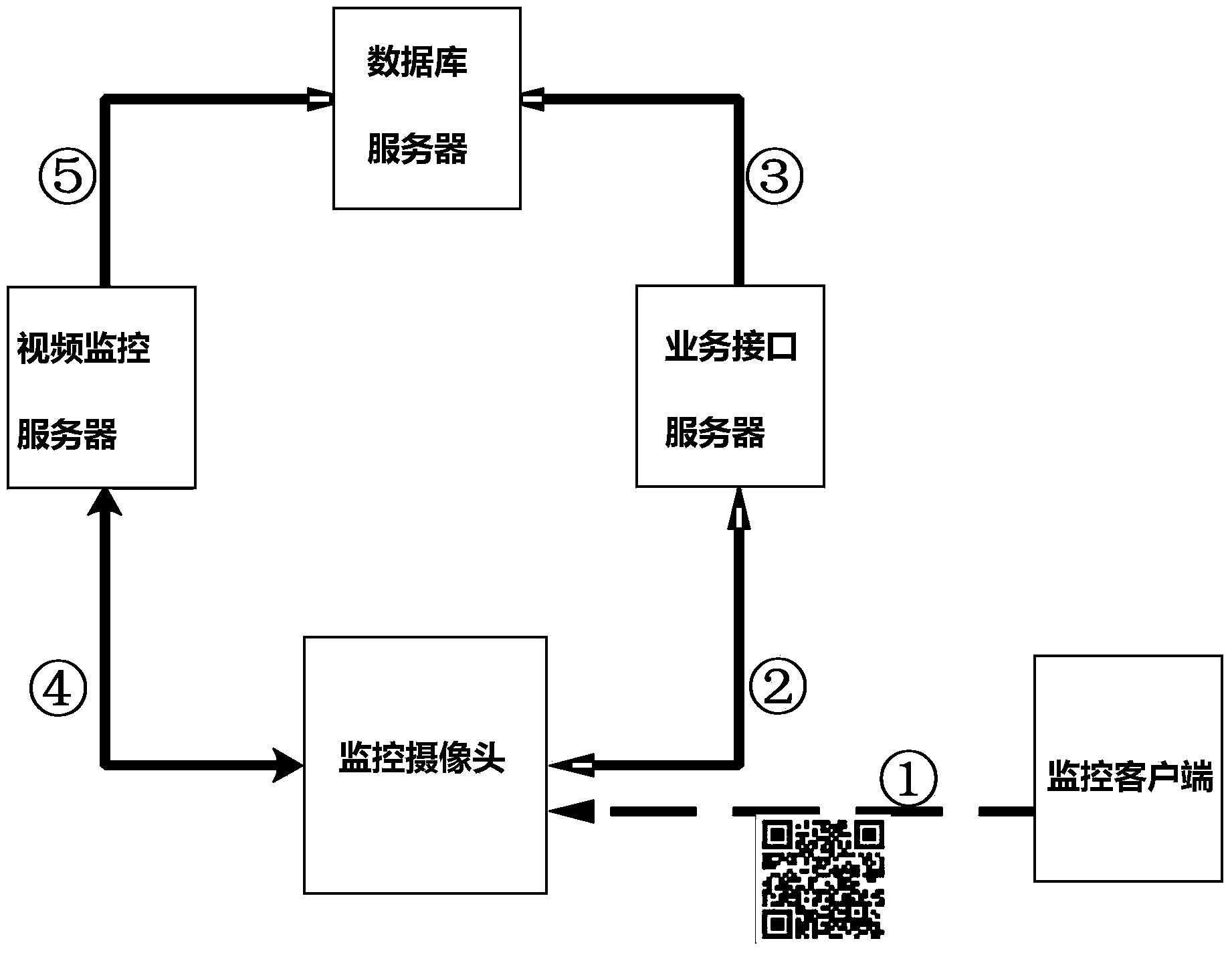
[0027] The video surveillance system of the present invention is made up of surveillance camera, surveillance client and surveillance server three parts, as figure 1 , 2 As shown, there can be one or more monitoring cameras, one or more monitoring clients, and the monitoring server is a virtual entity composed of a series of servers, which usually include business interface servers, video monitoring servers and databases server. Among them, the business interface server is the entry point of the server, which is used to register the monitoring client and the monitoring camera, and its address (domain name or IP) is pre-configured in the monitoring client and the monitoring camera; the video monitoring server is used for monitoring The camera keeps connected, receives the monitoring image sent by the monitoring camera, and forwards the required...


PUM


Abstract

The invention discloses a method for fast configuring a remote video monitoring system. The method comprises the steps that (1) a wireless network access module is arranged on a monitoring camera; (2) currently available wireless networks are scanned by a monitoring client, a wireless network is selected and a wireless network password is input; (3) after receiving authentication information of the monitoring client, a monitoring server sends a safety verification code to the monitoring client; (4) the monitoring client converts an access point name, the password, the safety verification code and the authentication information to a two-dimension code picture, and the two-dimension code picture is placed in a shooting area of the monitoring camera; (5) the two-dimension code picture is shot through the monitoring camera and is analyzed, the monitoring camera has access to the wireless network, and an equipment serial number, the safety verification code and the authentication information of the monitoring camera are then sent to the monitoring server; (6) authentication is conducted on the monitoring client by the monitoring server according to information sent by the monitoring camera, and when the certification is passed, the monitoring camera and the monitoring client are bound to enter a monitoring module.

Description

technical field [0001] The invention belongs to the technical field of video monitoring, in particular to a system for performing remote video monitoring through a network and a quick configuration method thereof. Background technique [0002] With the rapid development of computer networks, the remote video monitoring method of using the Internet to carry out remote video monitoring and presenting the monitoring results to users through computers and other equipment has been widely used. Since the installation and deployment of remote video surveillance systems involves a large number of steps and links such as equipment installation, network cable laying, network settings, and system debugging, such systems often need to be built by professional construction personnel, which is not only time-consuming and laborious, but also increases additional costs. Therefore, Small and micro enterprises and individual users often do not adopt it. At the same time, due to the complexit...

Claims


Application Information

Patent Timeline
IPC IPC(8): H04N7/18H04L29/06H04L29/08
Inventor 应凌云贺永林
Owner INST OF SOFTWARE - CHINESE ACAD OF SCI
Learn More