Device for changing an operating state of at least one switch element

A technology for switching components and operating states, applied to mechanical equipment, components with teeth, transmission devices, etc., can solve the problems of increasing operating system design costs and installation space requirements, and achieve less installation space requirements and low power loss Effect

Active Publication Date: 2013-11-27
ZF FRIEDRICHSHAFEN AG
View PDF7 Cites 11 Cited by
  • Summary
  • Abstract
  • Description
  • Claims
  • Application Information

AI Technical Summary

Problems solved by technology

[0016] In the known compensating mechanism, the compensating spring is in each case operatively connected to the turntable via an additional lever element, but the additional lever element undesirably increases the design complexity and installation space requirement of the operating system provided with the compensating mechanism

Method used


Image

  • Device for changing an operating state of at least one switch element
  • Device for changing an operating state of at least one switch element
  • Device for changing an operating state of at least one switch element

Examples


Embodiment Construction

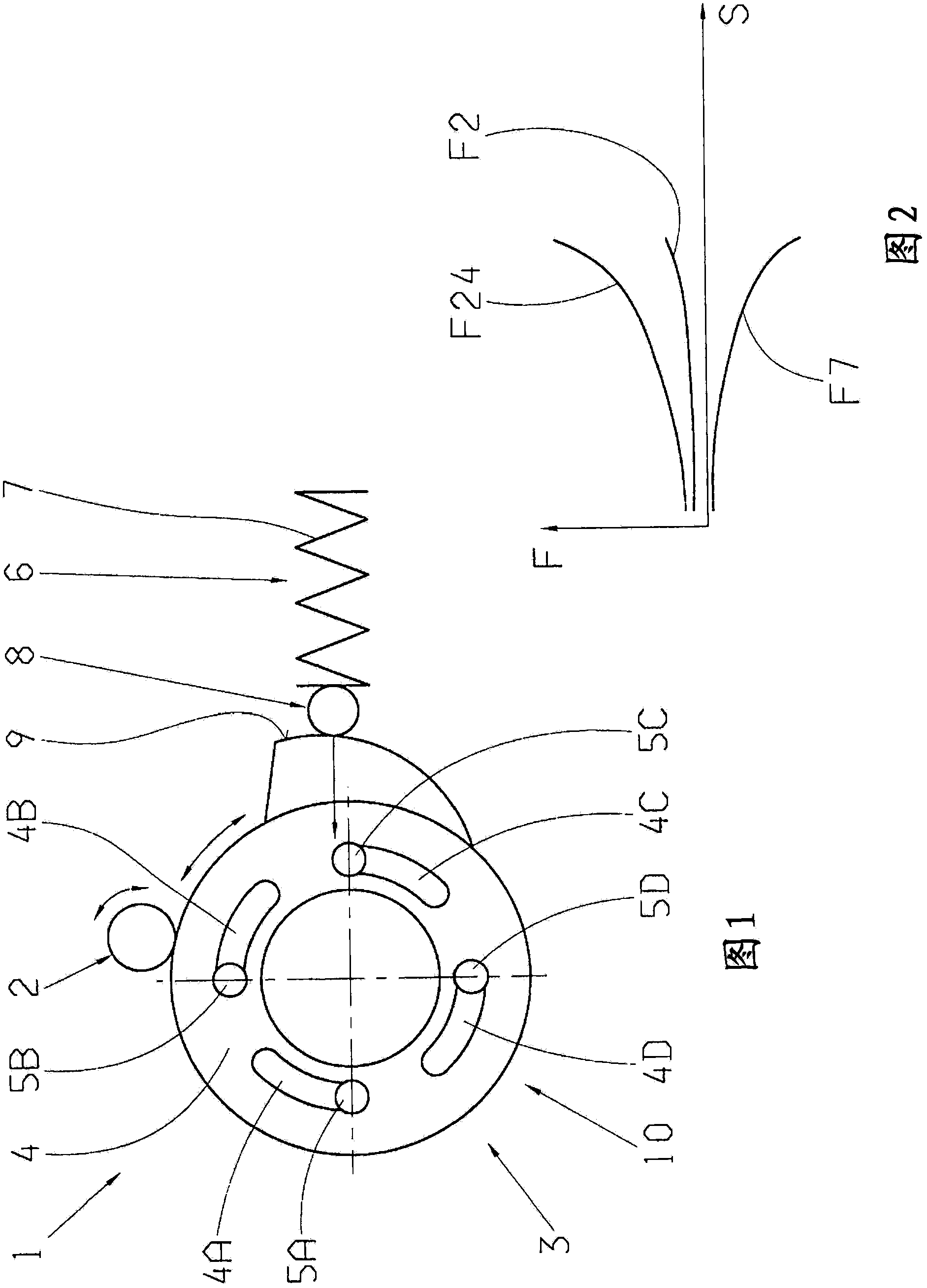
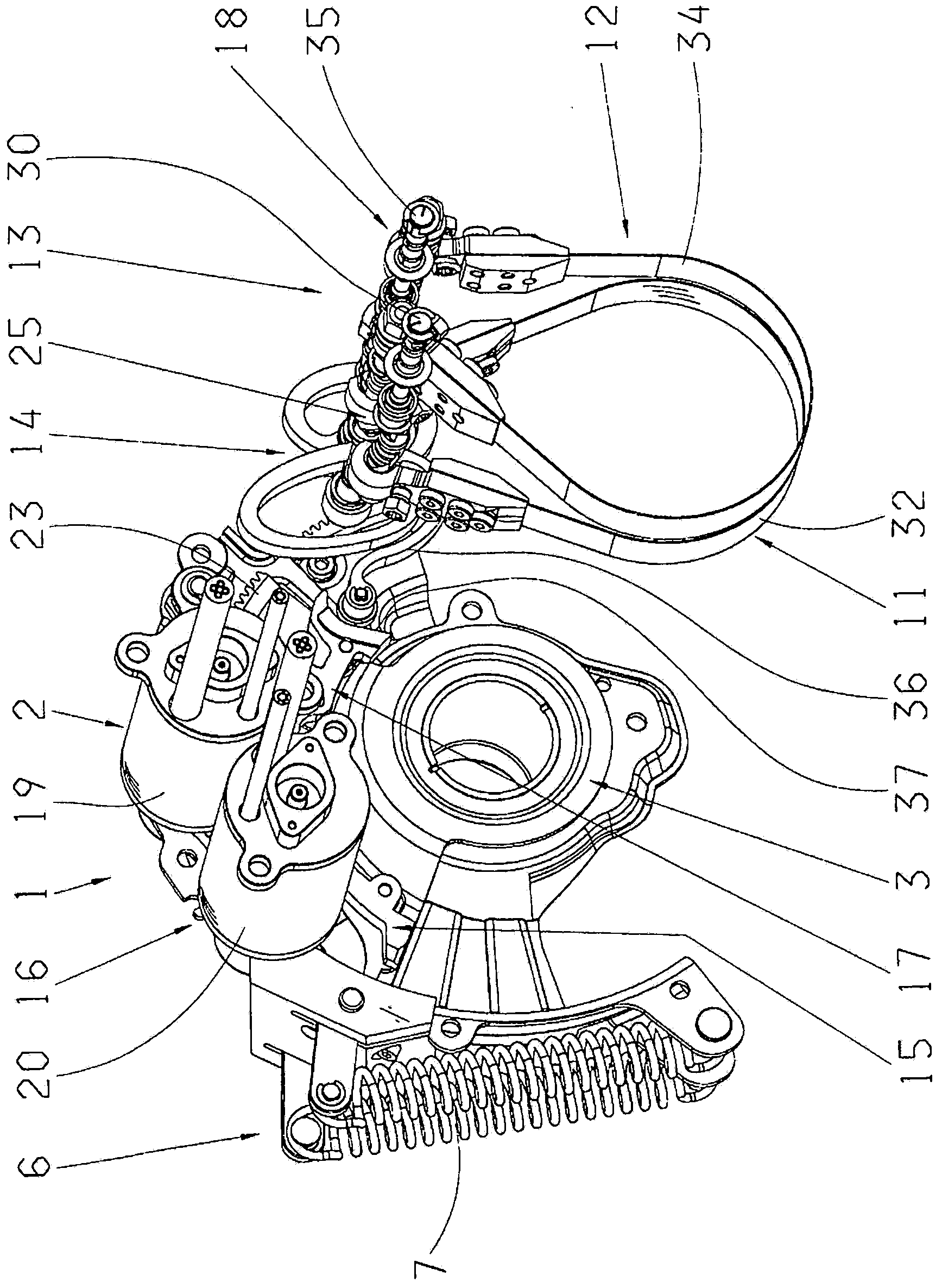
[0046] figure 1 A highly simplified schematic diagram of a device 1 for changing the operating state of a shifting element or for actuating a shifting element, for example in the form of a friction clutch, is shown. For actuating the switching element, the device 1 comprises a drive device 2, which in the present case is constructed as an electric motor and which in the figure 1 The drive mechanism, not shown in detail, and the drive conversion device 3 arranged between the drive mechanism and the switching element, in the region of the drive conversion device, the rotational drive movement of the drive mechanism can be converted into a translational operating movement of the switching element. Depending on the application, the drive device 2 can also be provided with a hydraulic motor or the like, by means of which the rotary drive required for actuating the switching element can be provided to the desired extent.

[0047] The drive conversion device 3 currently comprises tw...


PUM


Abstract

The invention relates to a device (1) for changing an operating state of at least one switch element, the switch element having two switch element halves that can be brought into operative connection with each other in order to connect at least two components, or that can be disengaged in order to cut the connection between the components. A device (6) is provided by means of which a force can be introduced into the actuating chain (10) between the switch element and a drive device (2), by means of which an actuating force can be provided for the switch element. The force of the device (6) can be introduced into an actuating chain (10) between the drive device (2) and the switch element in the area of a coupling area (8) of the device (6) that is in operative connection with a control curve (9). The coupling area (8) is in operative connection with the control curve (9) as a function of a rotational drive of the drive device (2) along a path of the control curve (9). The force that can be introduced by means of the device (6) varies as a function of the operating state, at least as a function of the path of the control curve (9).

Description

technical field [0001] The invention relates to a device for changing the operating state of a switching element according to the type defined in detail in the preamble of claim 1 . Background technique [0002] Transmission devices known from practice are generally provided with positive-locking and friction-locking shift elements, by means of which different functions of the transmission device are provided as a function of the operating state. For example, in a dual-clutch transmission, two shift elements in the form of friction-locking clutches are arranged on the transmission input side, via which a sub-transmission ready to be engaged can be inserted into the power flow of the vehicle drive system or can be activated in a corresponding manner. Disconnect from the force flow when changing the required transmission ratio. Also known are shifting elements designed as band brakes, by means of which, for example, the rotational speed of a shaft of a transmission arrangemen...

Claims


Application Information

Patent Timeline
Patent Type & Authority Applications(China)
IPC IPC(8): F16H61/12F16H61/28F16H63/18F16D21/00
CPCF16H2003/123F16H63/3003F16H2063/3056F16D2023/123F16H2061/0411F16D23/12F16H2061/1204F16H61/688
Inventor M·阿贝勒W·里格尔M·赖施P·雅尼加
Owner ZF FRIEDRICHSHAFEN AG
Why Eureka
Try Eureka