
Bending machine

A bending machine and roll bending technology, which is applied in the field of bending machines, can solve problems such as high technical requirements for workers, affect the flatness of products, and low production efficiency, and achieve low technical requirements for workers, realize standardized production, and be easy to operate. Effect

Inactive Publication Date: 2013-12-04
TIANJIN ZHIYONG TECH
View PDF6 Cites 11 Cited by
  • Summary
  • Abstract
  • Description
  • Claims
  • Application Information

AI Technical Summary

Problems solved by technology

This method is a serious waste of materials and requires multiple processes such as cutting, bending, welding, and grinding, all of which are done by hand. The work efficiency is low, the power consumption is large, the production cost is high, the technical requirements for workers are high, and the products are not refined enough.
The aluminum alloy sideband with folded edge on the upper side does not need to be welded, and various characters and graphics can be disassembled through the drawing software first, and the direction, position, angle and arc of the bend are automatically generated, and the professional sticky notes through the font The printer prints it out and pastes it on the sideband for bending, but the teeth must be cut when bending, and creases are often formed on the sideband after bending, which affects the flatness of the product
Since the above-mentioned teeth cutting and edge bending are also done by hand, this method also has the problems of low production efficiency and high technical requirements for workers. Even a skilled worker needs at least 2-2 hours of continuous work to make a letter case with a size of one square meter. 3 hours, low productivity

Method used


Image

  • Bending machine
  • Bending machine
  • Bending machine

Examples


Embodiment Construction

[0022] The present invention will be described in detail below with reference to the drawings and examples.

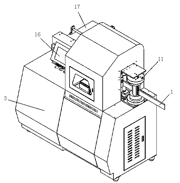
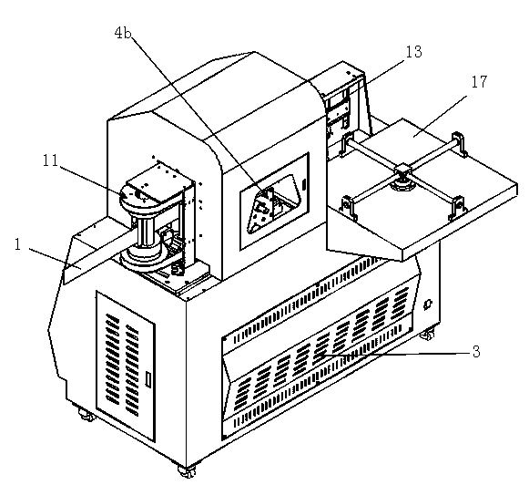
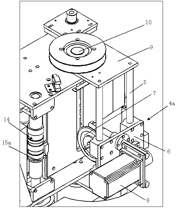
[0023] figure 1 It is a schematic diagram of the external structure of the bending machine of the present invention; figure 2 It is a structural schematic diagram of the back of the bending machine of the present invention; image 3 It is a partial enlarged view of the front slotting mechanism in the bending machine of the present invention; Figure 4 It is a partial enlarged view of the slotting mechanism in the plate conveying direction in the bending machine of the present invention; Figure 5 It is a partial enlarged view of the bending mechanism in the bending machine of the present invention.

[0024] Such as Figure 1 to Figure 5 As shown, the two ends of the bending machine of the present invention are respectively set as the feed end and the discharge end, and the sheet material 1 enters the bending machine from the feed end, and the processed sheet mater...


PUM


Abstract

Disclosed is a bending machine. The two ends of the bending machine are provided with a feeding end and a discharging end respectively. The bending machine comprises a machine frame, an electric control cabinet, a control mechanism, a grooving mechanism and a feeding mechanism. The grooving mechanism comprises a front-face grooving mechanism and a back-face grooving mechanism. An angle-turning mechanism fixedly provided with the front-face grooving mechanism can be driven by a rotating motor to rotate horizontally, therefore, a circular saw web in the front-face grooving mechanism swings in the horizontal direction within a certain range, the machining angle at the front-face protrusion portion of a board by the circular saw web is expanded, and the cut angle at the front-face protrusion portion of the board can be adjusted according to various bending angles of the board. The bending mechanism can continuously exert pressure on the board through a bending roller and an auxiliary bending roller when an external shaft sleeve rotates, and circular and smooth turning angles are formed on the board. When the bending machine is used for machining metal characters, the automation degree is higher, numerical control full-automatic production can be achieved, the process is simplified, and the production efficiency is greatly improved.

Description

technical field [0001] The invention relates to the technical field of sheet material processing, in particular to a bending machine which performs double-sided grooves on the sheet material and automatically bends the sheet material as required, thereby improving the production efficiency of metal advertising letter processing. Background technique [0002] Traditional advertising signs are mainly three types: inkjet signboards, copper and iron letters and neon lights. Neon lights are more beautiful at night, but they look very messy during the day, and they are difficult to install, consume a lot of power, and the light source is fragile. They are already in a period of decline. Although the cost of copper and iron letters is low, the three-dimensional effect is not strong. It does not look high-grade during the day, but it cannot be seen clearly at night. People have to install some high-wattage spotlights to illuminate it, which consumes a lot of power. The aesthetic ef...

Claims


Application Information

Patent Timeline
IPC IPC(8): B21D5/08B21D43/09B23D47/04
Inventor 韩云鹏韩云星
Owner TIANJIN ZHIYONG TECH
Learn More