Cradle and pay-off reel structure of cable-former stranding cage device

A pay-off reel and cable-forming machine technology, which is applied in the directions of transportation and packaging, conveying filamentous materials, thin material processing, etc., can solve problems such as elimination, affecting the working efficiency of the cable-forming machine, and increasing the cost of spare parts, and achieves Ensure tension, good damping force adjustment effect, cost saving effect

Active Publication Date: 2013-12-04
CHANGSHU CABLE WORKS
View PDF8 Cites 22 Cited by
  • Summary
  • Abstract
  • Description
  • Claims
  • Application Information

AI Technical Summary

Problems solved by technology

Although the cradle pay-off reel of this structure can meet the requirements for paying off wires during use, it has the disadvantage that the bearing bush 11 is easy to wear and needs to be replaced frequently. Frequent replacement of the bearing bush 11 will increase the cost of spare parts on the one hand, and affect the The working efficiency of the cable forming machine, because the replacement of the bearing bush 11 must be carried out when the cable forming machine is in a stopped state, and on the other hand, the work intensity of the mechanic (also known as equipment maintenance personnel) is increased.
[0004] by image 3 Take the right end of the shown position as an example. There are generally two types of wear of the above-mentioned bearing bush 11: one is the part where the central shaft 22 of the pay-off reel matches the bearing bush 11, that is, the part where the central shaft 22 of the pay-off reel extends into the bearing bush 11 Due to the friction between the central shaft 22 of the pay-off reel and the inner wall of the bearing bush 11, the bearing bush is worn out. Usually, it is necessary to replace the bearing bush 11 in about 20 to 30 days (eight hours per shift per day), especially if If the lubricating oil is not injected into the bearing bush 11 through the grease nozzle 112, the life of the bearing bush 11 will be shorter; the second is the wear of the bearing bush 11 that occurs between the centering sleeve 222 in the center shaft of the pay-off reel and the end face of the bearing bush 11, especially when When the capstan is erected according to the process requirements, the end face of the centering sleeve 222 in the center shaft of the pay-off reel faces the wear of the end face of the bearing bush 11.
[0005] Although the structure of the above-mentioned cradle pay-off reel has the disadvantage that the bearing bush 11 is vulnerable and needs to be replaced frequently, the industry generally regards it as a common situation, so this situation has not changed in the slightest so far.
[0006] The applicant searched the literature in order to solve the above problems. Although there are utility model authorization announcements CN201289763Y (a cable forming machine) and invention patent authorization announcements CN101885436B (a disc forming cable machine, cage cable forming machine and machine reel), but has not seen the enlightenment that can eliminate the technical problems mentioned above
In addition, implementing good damping on the pay-off reel is also an important factor that cannot be neglected, otherwise it will affect the reasonable tension of the wires released from the pay-off reel, but there is no corresponding technical inspiration in the prior art

Method used


Image

  • Cradle and pay-off reel structure of cable-former stranding cage device
  • Cradle and pay-off reel structure of cable-former stranding cage device
  • Cradle and pay-off reel structure of cable-former stranding cage device

Examples


Embodiment Construction

[0023] In order to enable the examiners of the patent office, especially the public, to understand the technical essence and beneficial effects of the present invention more clearly, the applicant will describe in detail the following in the form of examples, but none of the descriptions to the examples is an explanation of the solutions of the present invention. Any equivalent transformation made according to the concept of the present invention which is merely formal but not substantive shall be regarded as the scope of the technical solution of the present invention.

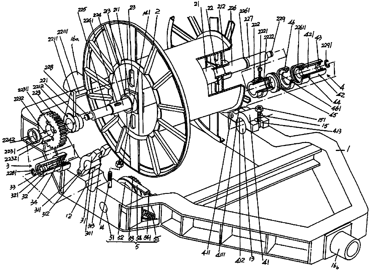
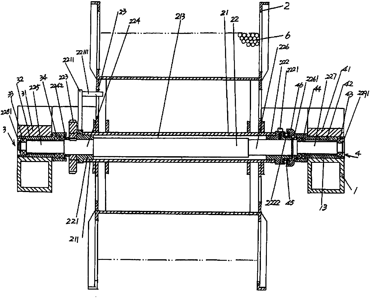
[0024] See figure 1 with figure 2 , a cradle 1 and a pay-off reel 2 belonging to the cradle pay-off reel structural system are given, and one end in the length direction of the cradle 1 is figure 1 The middle position of the left end of the shown position forms a first pivot connection seat 16a, and the other end in the length direction of the cradle 1 is figure 1 The middle position of the right end of...


PUM


Abstract

The invention discloses a cradle and pay-off reel structure of a cable-former stranding cage device and belongs to the technical field of electric wire and cable processing facilities. The cradle and pay-off reel structure of the cable-former stranding cage device comprises a cradle and a pay-off reel. The center of the pay-off reel is provided with a pay-off reel center shaft sleeve; one end of the pay-off reel center shaft sleeve forms an outer centring sleeve matching end; the other end of the pay-off reel center shaft sleeve forms an inner centring sleeve matching end; a pay-off reel center shaft outer centring sleeve is provided with a damping arm; the damping arm is fixedly provided with a deflector rod; a pay-off reel center shaft is fixedly provided with a damping gear. The cradle and pay-off reel structure of the cable-former stranding cage device is characterized in that one side of the cradle is provided with a pay-off reel center shaft outer pivotal bearing mechanism; the other side of the cradle is provided with a pay-off reel center shaft inner pivotal bearing mechanism; one end of the pay-off reel center shaft is supported to the pay-off reel center shaft outer pivotal bearing mechanism; the other end of the pay-off reel center shaft is supported to the pay-off reel center shaft inner pivotal bearing mechanism; one side of the cradle is provided with a damping gear regulating mechanism; the damping gear is matched with the damping gear regulating mechanism. The cost of spare parts is reduced, the working strength is reduced, the cabling efficiency is improved, and the tension of a lead released from the pay-off reel is ensured.

Description

technical field [0001] The invention belongs to the technical field of wire and cable processing facilities, and in particular relates to a cradle pay-off reel structure of a winch cage device for a cable forming machine. Background technique [0002] The process of twisting multiple wires according to the pitch required by the process to form a bundle or a strand is called cabling, and the equipment that realizes this process is usually called a cabling machine. The cable forming machine is the equipment commonly equipped by wire and cable manufacturers, and the cable forming machine can be divided into a stranding machine, a bundle type cable forming machine, a cage type cable forming machine and a disc type cable forming machine, etc. For small-sized multi-core cables, a twisting machine or a bundle-type cable forming machine is usually used, while for such as power cables, mining cables and marine cables, due to the relatively small amount of internal insulating cores, b...

Claims


Application Information

Patent Timeline
Patent Type & Authority Applications(China)
IPC IPC(8): B65H49/34B65H49/32
Inventor 陆康林
Owner CHANGSHU CABLE WORKS
Why Eureka
Try Eureka