Electronic lock system, and control method and power supply control method thereof

An electronic lock system and power supply control technology, applied in the field of security control, can solve the problems of the system cannot be opened normally, its own power consumption is large, and the reliability is low, so as to reduce the daily standby power consumption, low standby power consumption, and provide reliability Effect

Inactive Publication Date: 2013-12-04
WUHAN PULINGUANGTONG TECH
View PDF5 Cites 9 Cited by
  • Summary
  • Abstract
  • Description
  • Claims
  • Application Information

AI Technical Summary

Problems solved by technology

[0004] (1) Control and manage the electromagnetic gate valve that remains closed after power-on and opens after power-off. This type of system requires continuous power supply, has a large power consumption, and is affected by the power system, resulting in poor stability and reliability;
[0005] (2) Control and manage the electromagnetic gate valve that remains closed after power failure and opens when power is turned on. When the circuit control part of this type of system fails or the power supply system fails, the electromagnetic gate valve is locked and the system cannot be opened normally. less reliable
However, in terms of the specific control circuit design of the electronic lock system, no clear instructions have been given.

Method used


Image

  • Electronic lock system, and control method and power supply control method thereof
  • Electronic lock system, and control method and power supply control method thereof
  • Electronic lock system, and control method and power supply control method thereof

Examples


Embodiment 1

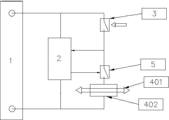
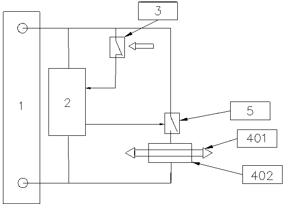
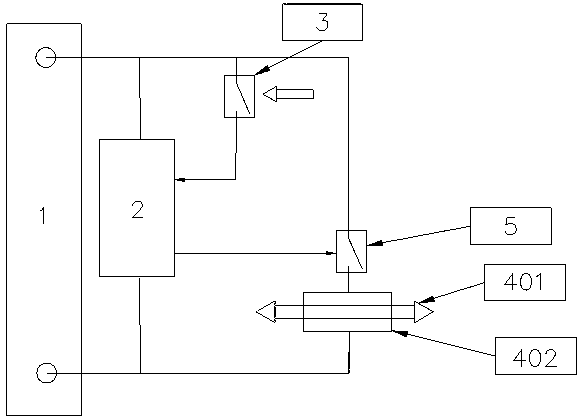
[0041] Embodiment 1. An electronic lock system, a power supply module (1) responsible for supplying power to other modules, a control module (2) responsible for controlling the operation of the entire system, and a trigger switch responsible for monitoring the state of key insertion or the state of the door opening button being triggered ( 3), the electronic lock shaft (4), which is opened in the initial state but makes the electronic lock system closed when it is closed, is controlled by the control module and is responsible for driving the drive circuit (5) of the electronic lock shaft, wherein the drive circuit is connected in series with the electronic lock shaft . Structural diagram such as figure 1 shown.

[0042] In this embodiment, the power supply module responsible for supplying power to other modules supplies power to a storage battery, or to a DC power supply, etc., and the specific implementation forms are not limited in the present invention.

[0043] In this e...

Embodiment 2

[0059] Embodiment 2. An electronic lock system. The difference between the electronic lock system of this embodiment and Embodiment 1 is that

[0060] The control module also includes a power supply control unit (201) capable of switching from the disconnection state to the conduction state after receiving the trigger signal sent by the trigger switch, and capable of maintaining itself. powered by.

[0061] Such as Figure 7 Shown is the circuit structure diagram of the power supply control unit when the trigger switch is in the normally off state; the power supply control unit is the control switch 1 (202) that is in the off state in the initial state; one end A of the control switch 1 is connected to one end of the power supply module Docking, the other end B is connected with the system control module, and is connected in parallel with the control end C of the control switch 1, and the control end C is also connected with the trigger switch at the same time, and receives t...

Embodiment 3

[0070] Embodiment 3. A control method for an electronic lock system, comprising:

[0071] A1. The driving circuit in the electronic lock system is disconnected in the initial state;

[0072] A2. When the trigger switch is triggered, the control module senses that the trigger switch is triggered;

[0073] A3. The control module will control the drive circuit to close or the forward power supply circuit to close, and the electronic lock shaft will be closed, so that the electronic lock system is in a locked state;

[0074] A4. If the control module obtains the door opening information, it will stop controlling the drive circuit or turn the drive circuit into a reverse power supply circuit, so that the electronic lock shaft returns to the open state, and the drive circuit returns to the state when it was disconnected. The electronic lock system can be turned on.

[0075] In this embodiment, for the description of the specific control method of the electronic lock system, refer ...


PUM


Abstract

The embodiment of the invention provides an electronic lock system, and a control method and a power supply control method thereof. In a daily state, an electronic lock shaft does not need power supply, a control module is in a standby or cut-off state, and an electronic lock system can keep lowest standby power consumption; once the electronic lock is required to be unlocked, the electronic lock shaft is closed in first time by using the electronic lock system, so that the electronic lock system is prevented from being opened illegally; once the electronic lock system fails, the electronic lock shaft is not controlled by the control module, so that the electronic lock system can be opened directly. The safety of the electronic lock system is ensured, the reliability of the electronic lock system is provided, meanwhile daily standby power consumption of the electronic lock system is lowered to the maximum extent, and the popularization and application of the type of electronic lock system are facilitated.

Description

technical field [0001] The invention relates to the technical field of security control, in particular to an electronic lock system, a control method thereof, and a power supply control method. Background technique [0002] Electronic door lock systems have been used in many fields, such as electronic access control systems in the field of security control, cabinet access control systems in the field of automatic control, etc. Electronic door lock systems have already existed as an indispensable method. [0003] Traditional electronic door lock systems often use the following two methods: [0004] (1) Control and manage the electromagnetic gate valve that remains closed after power-on and opens after power-off. This type of system requires continuous power supply, has a large power consumption, and is affected by the power system, resulting in poor stability and reliability; [0005] (2) Control and manage the electromagnetic gate valve that remains closed after power failu...

Claims


Application Information

Patent Timeline
Patent Type & Authority Applications(China)
IPC IPC(8): E05B49/02
Inventor 徐志国
Owner WUHAN PULINGUANGTONG TECH
Why Eureka
Try Eureka