Hydraulic damper with adjustable damping

A hydraulic shock absorber and damping technology, which is applied in the field of hydraulic shock absorbers, can solve problems such as low service life, complex structure, and unstable shock absorber performance, and achieve the effects of low requirements, improved comfort, and easy maintenance and promotion

Inactive Publication Date: 2013-12-04
JIANGSU UNIV
View PDF6 Cites 14 Cited by
  • Summary
  • Abstract
  • Description
  • Claims
  • Application Information

AI Technical Summary

Problems solved by technology

[0003] In order to solve the above problems, the present invention provides a hydraulic shock absorber with adjustable damping, whi

Method used


Image

  • Hydraulic damper with adjustable damping
  • Hydraulic damper with adjustable damping
  • Hydraulic damper with adjustable damping

Examples


Embodiment Construction

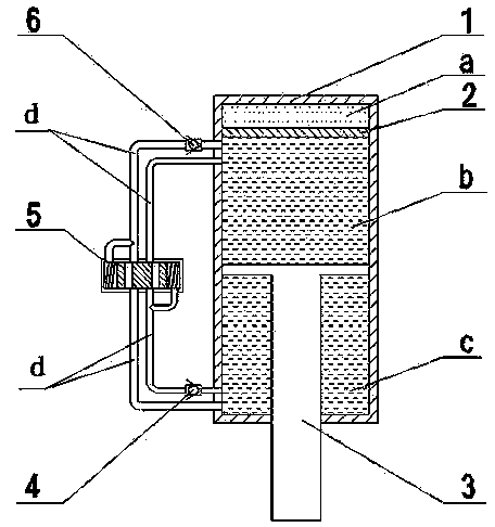
[0016] Such as figure 1 As shown, the shock absorber with adjustable damping of the present invention includes a cylinder 1 , a floating piston 2 and a piston 3 . Wherein the floating piston 2 is in the cylinder body 1, is located at the top of the piston 3, and is in sealing contact with the inner wall of the cylinder body 1. The piston rod at the bottom of the piston 3 protrudes from the bottom of the cylinder 1 to the outside of the cylinder 1, and the piston 3 has a 1mm through hole, and the top of the piston 3 is in sealing contact with the inner wall of the cylinder 1. The floating piston 2 and the piston 3 divide the cylinder body 1 into three chambers, namely the upper compressed air chamber a, the middle upper oil chamber b and the lower lower oil chamber c. The compressed air chamber a is used to compensate for the reduction of the oil storage volume of the cylinder 1 due to the upward movement of the piston 3 (compression stroke) into the cylinder 1. Outside the c...


PUM


Abstract

The invention discloses a hydraulic damper with adjustable damping. The hydraulic damper is arranged on an automobile. A hydraulic loop d is connected between an upper oil cavity b and a lower oil cavity c. An oil pressure cavity is arranged on the hydraulic loop d and comprises an oil pressure chamber, a piston valve core and two springs. The piston valve core and the two springs are arranged in the oil pressure chamber. The piston valve core divides the oil pressure cavity into a chamber e and a chamber f. Two through holes are formed in the piston valve core. The front end of a pipeline d1 is connected with the upper oil cavity b, and the tail end of the pipeline d1 is connected with the oil pressure cavity and is connected with a pipeline d3 in a bypass mode. The pipeline d3 is connected with the chamber f. A pipeline d6 is connected with the chamber f and the lower oil cavity c. The front end of a pipeline d5 is connected with the lower oil cavity c, and the tail end of the pipeline d5 is connected with the oil pressure cavity and is connected with a pipeline d4 in a bypass mode. The pipeline d4 is connected with the chamber e. A pipeline d2 is connected with the chamber e and the upper oil cavity b. Pressure difference between the two ends of the oil pressure chamber is used for pushing the piston valve core to move, so that the communication area of an oil pipe and the piston valve core is changed, the speed of oil liquid is changed when the oil liquid passes through the piston valve core, so that damping is changed, and accordingly a damping value is automatically adjusted according to road conditions in real time.

Description

technical field [0001] The invention relates to a shock absorber installed on an automobile, in particular to a hydraulic shock absorber with adjustable damping. Background technique [0002] In order to speed up the attenuation of the vibration of the frame and the body to improve the ride comfort of the car, shock absorbers are installed inside the suspension system of most cars. The basic principle of the shock absorber is to use damping to consume the energy generated in the vibration to achieve vibration reduction. The hydraulic shock absorber uses the small hole throttling fluid damping technology to realize the damping characteristics of the suspension system. The cylinder barrel also reciprocates, so that the oil in the housing repeatedly flows from one inner cavity through some narrow pores into the other inner cavity. At this time, the friction between the hole wall and the oil and the internal friction of the liquid molecules are formed. The damping force on vib...

Claims


Application Information

Patent Timeline
IPC IPC(8): F16F9/512F16F9/19
Inventor 李仲兴陈望孙益
Owner JIANGSU UNIV
Why Eureka
Try Eureka