
LED lamp heat dissipation structure and LED energy-saving lamp with same

A technology for LED lamps and heat dissipation structures, applied in lighting and heating equipment, cooling/heating devices of lighting devices, lighting devices, etc. Short and other problems, to achieve the effect of convenient and fast installation, disassembly and maintenance operations, improve power and service life, work stability of LED lights, and high production efficiency

Inactive Publication Date: 2013-12-04
NINGBO YONGJING ENERGY SAVING TECH
View PDF5 Cites 3 Cited by
  • Summary
  • Abstract
  • Description
  • Claims
  • Application Information

AI Technical Summary

Problems solved by technology

[0003] The present invention solves the problem that the heat dissipation structure of the existing LED lighting products has a poor heat dissipation effect on the LED chip, and the heat dissipation is not timely, the heat dissipation effect is poor, and it is easy to cause the temperature of the LED chip of the lamp to be too high and burn out the chip. The service life of the LED chip is shortened, and ultimately the service life and performance of the entire LED energy-saving lamp are reduced. The current situation provides a method that can improve the heat dissipation effect of the LED chip to a greater extent, and achieve the goal of improving the working performance and service life of the LED chip. Heat dissipation structure of LED lamp and LED energy-saving lamp adopting the heat dissipation structure

Method used


Image

  • LED lamp heat dissipation structure and LED energy-saving lamp with same
  • LED lamp heat dissipation structure and LED energy-saving lamp with same
  • LED lamp heat dissipation structure and LED energy-saving lamp with same

Examples


Embodiment 1

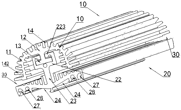
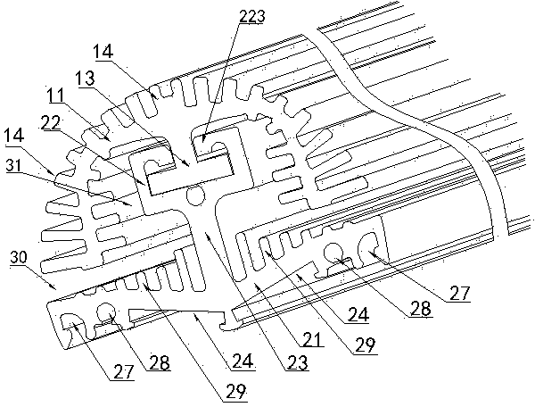
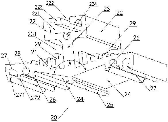
[0024] figure 1 , figure 2 , image 3 , Figure 4 In the shown embodiment, a heat dissipation structure of an LED lamp includes a first heat dissipation member 10 and a second heat dissipation member 20, wherein the first heat dissipation member 10 is the outer heat dissipation member of the LED lamp heat dissipation structure, and the second heat dissipation member 20 is an LED The inner heat dissipation member of the lamp heat dissipation structure, the inner surface of the second heat dissipation member 20 is provided with an LED chip mounting groove 24 for installing LED chips; the outer surface of the second heat dissipation member 20 is connected with a plurality of protruding second heat dissipation The fins 29 are connected with the first heat dissipation member 10 on the outer side of the second heat dissipation member 20, and the first heat dissipation member main body 11 of the first heat dissipation member 10 is a symmetrical arc-shaped body placed upside down ...

Embodiment 2

[0026] Figure 6 In the illustrated embodiment, the first heat dissipation member 10 and the second heat dissipation member 20 are integrally formed with each other, and there is a gap between the inner top of the first heat dissipation member 10 and the outer middle part of the second heat dissipation member 20. The connecting straight arm 123 connecting the first heat dissipation member 10 and the second heat dissipation member 20 (see Figure 6), directly connect the first heat dissipation member 10 and the second heat dissipation member 20 of the inverted U-shaped body by connecting the straight arm 123 to form an integrally formed inner and outer heat dissipation structure, and the others are the same as the first embodiment. The air flow at the inner groove of the first heat dissipation member 10 can be increased, so that the heat generated after the LED chip heats up can quickly reach radiation and convection into the air, so as to effectively improve the evacuation eff...

Embodiment 3

[0028] Figure 5 In the shown embodiment, an LED energy-saving lamp includes an LED lamp diffuser cover 50 and a power input control box 30, and adopts the LED lamp heat dissipation structure described in Embodiment 1 or Embodiment 2. After the fastening block 51 on the LED light diffusion cover 50 is fastened to the fastening slot 27 on the LED light diffusion cover 50, a power input control box 30 with a power plug is installed at the front end, and a tail end cover 40 is installed at the rear end. 1. The LED lamp diffusion cover 50 and the LED lamp heat dissipation structure formed by the connection of the first heat dissipation member 10 and the second heat dissipation member 20 are assembled into an LED energy-saving lamp, and the others are the same as the first embodiment.


PUM


Abstract

The invention discloses an LED lamp heat dissipation structure and an LED energy-saving lamp with the same. A first heat dissipation component is an outer side heat dissipation component of the LED lamp heat dissipation structure, and a second heat dissipation component is an inner side heat dissipation component of the LED lamp heat dissipation structure; a plurality of protruding second heat dissipation fins are distributed on the outer side face of the second heat dissipation component in a connected mode, the first heat dissipation component is arranged on the outer side of the second heat dissipation component in a connected mode, a plurality of protruding first heat dissipation fins are distributed on the inner side face and the outer side face of the body of the first heat dissipation component in a connected mode, and heat dissipation height separation space where heat generated when an LED chip works is rapidly conducted to the second heat dissipation component and radiated in convective air is reserved between the bottom end of the inverted first heat dissipation component and the outer side of the second heat dissipation component. The LED lamp heat dissipation structure has sufficient heat dissipation areas, has more heat dissipation areas than a conventional heat dissipation aluminum piece, has more convective air mass flow, can rapidly produce cross ventilation of an inner cavity and an outer cavity of the heat dissipation aluminum piece, and reaches the effect that the heat is rapidly scattered.

Description

technical field [0001] The invention relates to an LED lamp, in particular to a heat dissipation structure used in the LED lamp and an LED energy-saving lamp adopting the heat dissipation structure. Background technique [0002] Light-emitting diodes (LEDs) are widely used in lighting fixtures and electronic devices as light sources because of their advantages such as high brightness, low power consumption, and long service life; LED lighting technology is also increasingly used in office buildings , Shopping malls, supermarkets, schools, hospitals, hotels, factory workshops, homes and other indoor and outdoor lighting places, almost completely replace traditional fluorescent lamps; while the heat dissipation structure of LED lighting products on the existing market is generally composed of aluminum substrates, cooling fins Chips and other components to realize the heat dissipation effect on the LED chip, but the heat dissipation structure of this kind of LED lamp has a poor...

Claims


Application Information

Patent Timeline
Patent Type & Authority Applications(China)
IPC IPC(8): F21V29/00F21Y101/02F21V29/75
Inventor 郑忠义
Owner NINGBO YONGJING ENERGY SAVING TECH
Learn More