Fault detection method for Hall position sensors

A technology of sensor failure and Hall position, applied in the direction of instruments, measuring electricity, measuring devices, etc., can solve the problems of simple detection method and low reliability, and achieve the effect of low optimization cost, good effect, and low false alarm rate

Active Publication Date: 2013-12-04
NORTHWESTERN POLYTECHNICAL UNIV
View PDF5 Cites 31 Cited by
  • Summary
  • Abstract
  • Description
  • Claims
  • Application Information

AI Technical Summary

Problems solved by technology

[0004] In order to overcome the defects that the fault detection method of the Hall position sensor in the prior art is easily affected by interference, the detection method is too simple and has low reliability, the present invention proposes a fault detection method for the Hall position sensor, which can compreh...

Method used


Image

  • Fault detection method for Hall position sensors
  • Fault detection method for Hall position sensors
  • Fault detection method for Hall position sensors

Examples


Embodiment Construction

[0028] This embodiment is a fault detection method of a Hall position sensor.

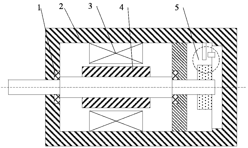
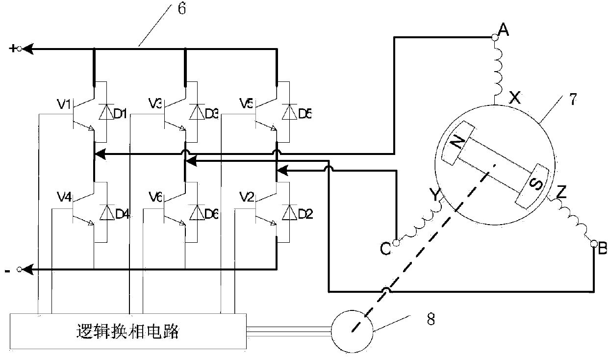
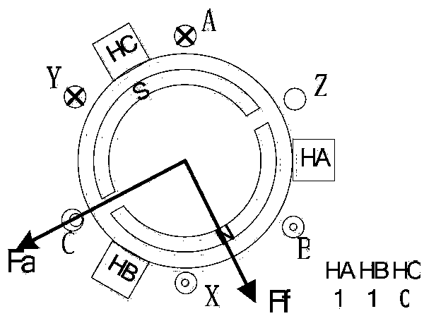
[0029] refer to figure 1 , figure 2 , figure 1 It is a structural schematic diagram of a brushless DC motor. It can be seen from the figure that the position sensor is located inside the motor body, which is easily affected by strong magnetic fields and vibrations, and is prone to failure. The control system of the brushless DC motor adopts a three-phase full-bridge structure, such as figure 2 As shown, T1-T6 are power switch tubes, and D1-D6 are freewheeling diodes. Using this topology, different magnetic potentials can be generated through different switch combinations to drive the motor to rotate. The commutation process of the brushless DC motor and the corresponding Hall switch state are as follows: Figure 3-a~Figure 3-f shown.

[0030] In this embodiment, TMS320F2812 is used as the main control chip, IR2130 is used as the driving chip, and a three-phase bridge inverter circuit and a c...


PUM


Abstract

The invention discloses a fault detection method for Hall position sensors. The method is available for comprehensively and accurately detecting Hall sensor faults and accurately locating faults of motor Hall position sensors; a user can replace the failed Hall sensor timely and accurately according to fault information. The method includes initializing variables, giving PSWM wave with proper duty ratio, controlling a motor drive module to allow a driver to operate, observing a value of an array when a motor stops rotating, comprehensively judging Hall state, and accurately detecting the fault of the Hall sensor so as to provide forcible support for fault identification and system reconfiguration. Compared with the traditional methods of detecting only whether the Hall sensors are all in high level or low level or not, the method has the advantages that the method is simple and practical, false alarm rate is low, modification on hardware circuits is avoided, the effect can be good just after software is optimized, and optimization cost is low.

Description

technical field [0001] The invention relates to a fault detection method of a brushless direct current motor, in particular to a fault detection method of a Hall position sensor. Background technique [0002] The basic structure of a brushless DC motor consists of a motor body, a controller and a position sensor. The position sensor is also the main sign different from the brushed DC motor. Its function is to detect the position of the main rotor during the movement process, convert the position signal of the rotor magnetic steel pole into an electrical signal, and provide correct commutation information for the logic switch circuit. To control their on and off, the current in the armature winding of the motor commutates in sequence with the change of the rotor position, forming a step-by-step rotating magnetic field in the air gap, driving the permanent magnet rotor to rotate continuously. The permanent magnet poles or field windings of traditional brushed DC motors are lo...

Claims


Application Information

Patent Timeline
IPC IPC(8): G01R31/00
Inventor 相里康马瑞卿张庆超韩伟键
Owner NORTHWESTERN POLYTECHNICAL UNIV
Why Eureka
Try Eureka