
Optical components and methods of use

An optical component and optical technology, applied in optical components, optics, installation, etc., can solve the problem that the optical lens cannot be finely adjusted, the optical quality of the projector is affected, and the light source processing effect of the optical lens 11 and the laser light source 14 cannot be effectively improved, etc. problems, to achieve the effect of improving production efficiency and improving optical quality

Inactive Publication Date: 2016-02-03
DELTA ELECTRONICS INC
View PDF6 Cites 0 Cited by
  • Summary
  • Abstract
  • Description
  • Claims
  • Application Information

AI Technical Summary

Problems solved by technology

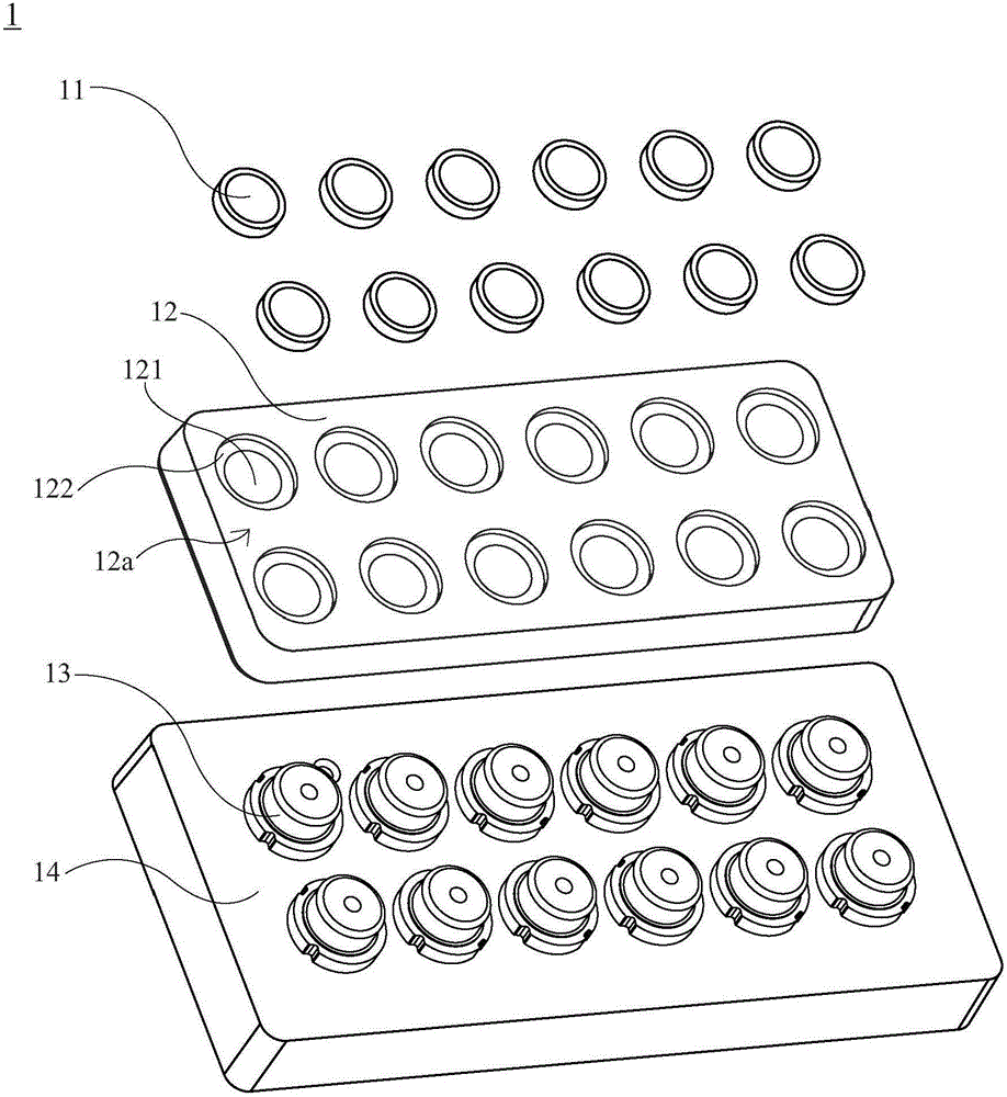
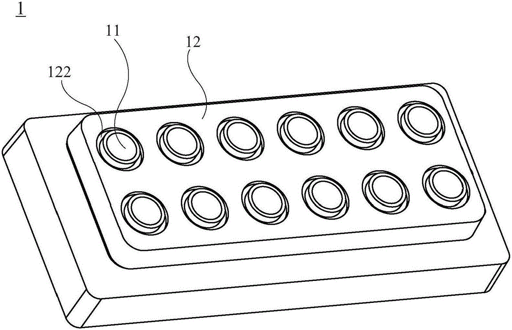
like Figure 1B As shown, although the position of the lens 11 on the carrying portion 122 is also based on the optical path between the optical lens 11 and the laser light source 14, the carrying portion 122 is pre-designed on the lens base 12, but the position of the lens 11 may still be different from that of the laser light source. 14 has a deviation in the optical path, but the existing laser light source device 1 has been unable to fine-tune the optical lens 11, so the light source processing effect of the optical lens 11 and the laser light source 14 has not been effectively improved, which in turn affects the performance of the projector. optical quality

Method used


Image

  • Optical components and methods of use
  • Optical components and methods of use
  • Optical components and methods of use

Examples


Embodiment Construction

[0040] For the convenience of description, the content of the present invention will be explained through the following examples. However, the description of the examples is only to illustrate the technical content of the present invention and its purpose and effect, rather than to directly limit the present invention. It should be noted that the dimensions and relative positions of the components in the illustrations are only for illustrative purposes, and are not intended to limit the proportions and dimensions of the implementation.

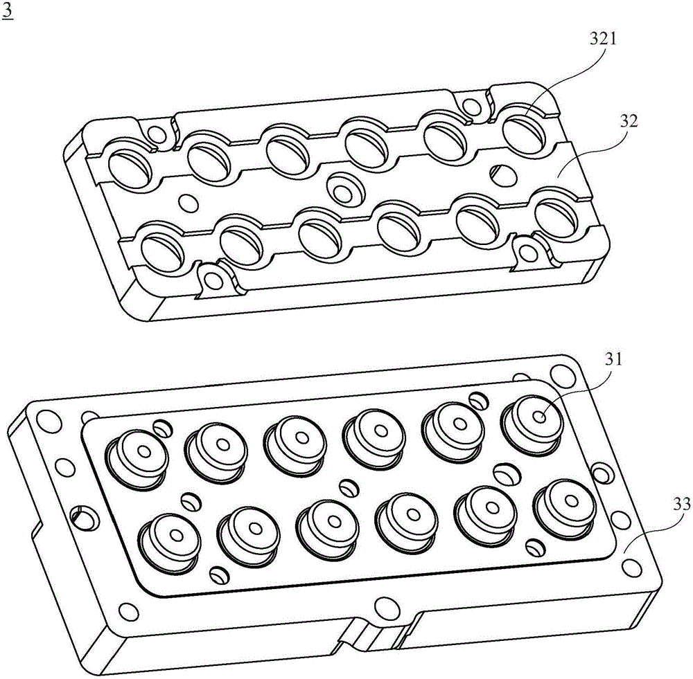
[0041] Figure 2A It is an exploded schematic view of the light source system of the present invention, Figure 2B to Figure 2D It is a schematic diagram of the application of the optical component of the present invention to a light source system, image 3 It is an enlarged schematic diagram of the optical assembly of the present invention, Figure 4 It is a schematic flow diagram of the method of using the optical component.

[0042] Plea...


PUM


Abstract

The invention proposes an optical component for a light source system and its usage method. The light source system includes a plurality of laser light sources, the optical component includes a carrier and a lens, and the lens is combined in the periphery of an inner diameter part of the carrier. Wherein, the lens is moved by means of the carrier, so that the position of the lens corresponds to the optical path of the laser light source, and the lens is relatively located above the laser light source. The optical component and its use method of the present invention can precisely and finely adjust the position of the lens after the carrier is clamped by the automatic instrument, so that the position of the lens and the optical path of the laser light source can achieve the best optical conversion effect, Thereby, the optical quality of the light source system can be effectively improved, and the production efficiency of the light source system can be enhanced.

Description

technical field [0001] The present invention relates to an optical component and its use method, in particular to an optical component applied to a laser light source and its use method. Background technique [0002] Early projectors that used white light bulbs as the main light source not only made the projector bulky, but also generated high heat during operation, which easily caused damage to the projector. With the development of technology, the current laser light source can produce high-intensity and stable light source, and has the advantages of wide color gamut and bright colors. Therefore, the laser light source gradually replaces the traditional light bulb, not only can effectively reduce the size of the projector, but also can produce Bright picture quality, so the application of laser light sources on projectors has become a trend. [0003] Such as Figure 1A As shown, it is an exploded schematic diagram of the existing laser light source device 1, including a p...

Claims


Application Information

Patent Timeline
Patent Type & Authority Patents(China)
IPC IPC(8): G03B21/14G02B7/02
Inventor 许茂山吴国栋林文岳
Owner DELTA ELECTRONICS INC
Learn More