
Test device and test method for C interface signals of lineside electronic unit (LEU)

A technology for interface signals and test equipment, applied in the field of C interface signal test equipment of LEU, can solve the problems of inconvenience, large environmental space requirements, and many auxiliary test equipment requirements, and achieve the effect of being convenient to carry, light in weight, and easy to promote.

Active Publication Date: 2013-12-04
BEIJING JIAODA SIGNAL TECH
View PDF3 Cites 13 Cited by
  • Summary
  • Abstract
  • Description
  • Claims
  • Application Information

AI Technical Summary

Problems solved by technology

[0003] At present, the commonly used instrument for testing the output signal of the C interface of the LEU is an oscilloscope, but the oscilloscope is a precision instrument and requires an AC220V power supply. It requires more auxiliary test equipment and requires a large environmental space, especially inconvenient for outdoor and trackside operations.

Method used


Image

  • Test device and test method for C interface signals of lineside electronic unit (LEU)
  • Test device and test method for C interface signals of lineside electronic unit (LEU)
  • Test device and test method for C interface signals of lineside electronic unit (LEU)

Examples


Embodiment Construction

[0016] In order to make the purpose, technical solutions and advantages of the present invention clearer, the technical solutions in the embodiments of the present invention will be further described in detail below in conjunction with the drawings in the embodiments. Obviously, the described embodiments are part of the implementation of the present invention. example, not all examples. Here, the exemplary embodiments of the present invention and their descriptions are mainly used to explain the present invention, but not to limit the present invention.

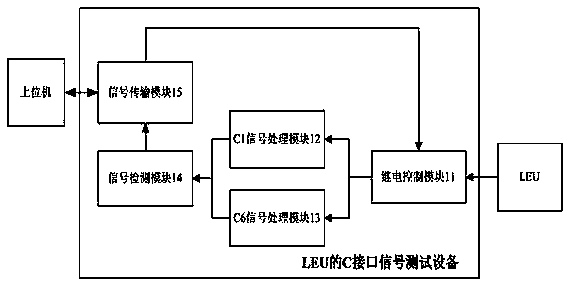
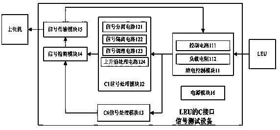
[0017] figure 1 It is the C-interface signal testing equipment of the LEU of the embodiment of the present invention, including a relay control module 11, a C1 signal processing module 12, a C6 signal processing module 13, a signal detection module 14 and an SCI communication module 15;

[0018] Wherein, the relay control module 11 is used to adjust the load resistance of the C interface signal input of the LEU;

[0019] C1...


PUM


Abstract

The invention discloses a test device and test method for C interface signals of a lineside electronic unit (LEU). The test device comprises a relay control module, a C1 signal processing module, a C6 signal processing module, a signal detection module and a serial communication interface (SCI) communication module, wherein the relay control module is used for adjusting load resistance input by the C interface signals; the C1 signal processing module is used for collecting C1 signals in the C interface signals which pass through the relay control module and processing the C1 signals; the C6 signal processing module is used for collecting C6 signals in the C interface signals which pass through the relay control module and processing the C6 signals; the signal detection module is used for detecting parameters of the C1 signals and parameters of the C6 signals and extracting message information and the error rate; and the SCI communication module is used for achieving communication between the C interface signal test device and an upper computer. Precision meters do not need to be prepared independently when the test device is utilized to test the C interface signals, and the C interface signals can be measured conveniently and rapidly; due to the fact that the test device is small in size and convenient to carry and power supply is simple, outdoor and trackside operation is facilitated, and the test device further has the advantages of being simple and convenient to operate and low in power consumption and cost and the like.

Description

technical field [0001] The invention relates to the field of railway communication signals, in particular to a C-interface signal testing device and a testing method of an LEU. Background technique [0002] The point transponder system has been widely used in the domestic CTCS system, passenger dedicated line, shunting protection system and CBTC system. Passive balise), where the interface between LEU and active balise is C interface, C1 interface and C6 interface are sub-interfaces of C interface respectively, LEU transmits train control information to active balise through C interface, but currently There is a lack of equipment specially used to test the output signal indicators of the C interface of the LEU. [0003] At present, the commonly used instrument for testing the output signal of the C interface of the LEU is an oscilloscope, but the oscilloscope is a precision instrument and requires an AC220V power supply. It requires more auxiliary test equipment and require...

Claims


Application Information

Patent Timeline
Patent Type & Authority Applications(China)
IPC IPC(8): H04B17/00G01R31/28
Inventor 闫炜祎刘浩郭超家天龙
Owner BEIJING JIAODA SIGNAL TECH
Learn More