Method for manufacturing solid three-dimensional concrete block and method for laying concrete tracks using concrete block manufactured using the method

A concrete block and concrete technology, which is applied in the directions of laying track, track, track maintenance, etc., can solve the problems such as the inability of prefabricated blocks to achieve plane and linear consistency, the decrease of track structure stability, and the increase of mortar filling amount.

Inactive Publication Date: 2013-12-04
姜南勋
View PDF7 Cites 4 Cited by
  • Summary
  • Abstract
  • Description
  • Claims
  • Application Information

AI Technical Summary

Problems solved by technology

[0018] As mentioned above, the consistency of plane alignment, longitudinal alignment and alignment cannot be achieved with traditional prefabricated blocks, and due to the irregular distance from the surface of the ballast bed, a separate operation of filling the gap is required, which increases the amount of mortar filling
[0019] Furthermore, in the case of conventional on-site construction, ballast is formed by pouring concrete while the sleeper is first formed and suspended, however, the concrete is not tightly packed between the sleeper and the ballast, resulting in poor adhesion, and as a result, in A gap is created between them, causing a decrease in the stability of the track structure

Method used


Image

  • Method for manufacturing solid three-dimensional concrete block and method for laying concrete tracks using concrete block manufactured using the method
  • Method for manufacturing solid three-dimensional concrete block and method for laying concrete tracks using concrete block manufactured using the method
  • Method for manufacturing solid three-dimensional concrete block and method for laying concrete tracks using concrete block manufactured using the method

Examples


Embodiment Construction

[0049] Exemplary embodiments of the present invention will be described in more detail below with reference to the accompanying drawings. However, the embodiments to be described below are exemplary, and the present invention is described in detail only to the extent that those skilled in the art to which the present invention pertains can easily implement the present invention, and thus, the protection scope of the present invention is not limited thereto. In addition, in the description of several embodiments of the present invention, constituent elements having the same technical features are denoted by the same reference numerals.

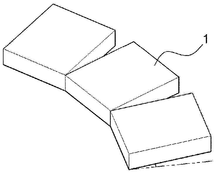
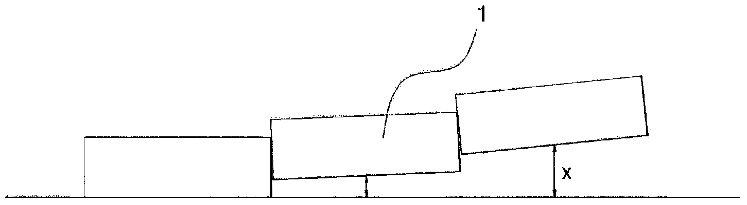
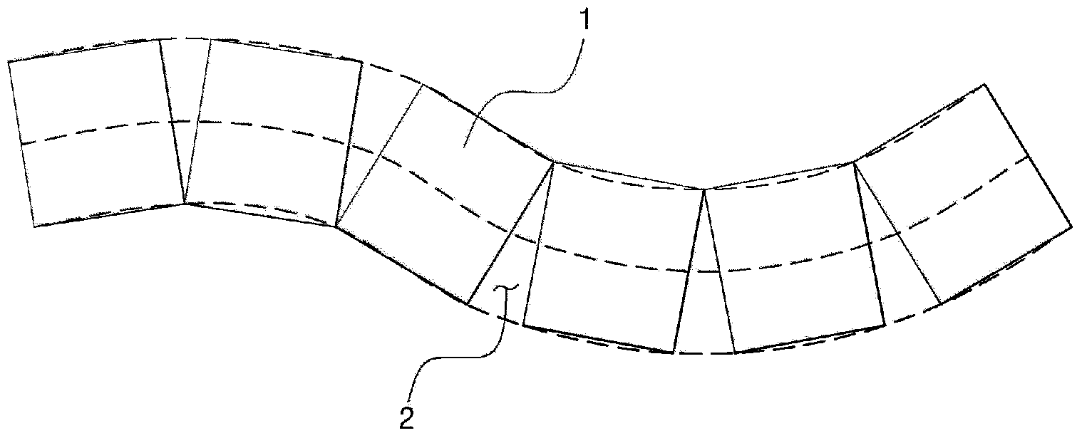
[0050] like figure 2 As shown, the method for manufacturing an integral three-dimensional concrete block according to an exemplary embodiment of the present invention includes the following steps: measuring the site alignment; installing the first temporary assembly support device; installing the first temporary rail; installing the first mold...


PUM


Abstract

The present invention relates to a method for manufacturing a concrete block, comprising the steps of: measuring the planned alignment considering the horizontal alignment, slope and cant of a site on which railway tracks are to be laid; arranging a plurality of first temporary assembly supports corresponding to the measured horizontal alignment; installing first temporary rails on the first temporary assembly supports, and adjusting the slope and cant in between the first temporary rails to correspond to the measured slope and cant; installing a plurality of first molds on the first temporary rails, following along therewith, so that the slope and cant correspond to the measured slope and cant; installing a pair of second molds along the longitudinal direction of the first temporary rails, thereby closing off the upper lateral sides of the first molds; arranging, to the horizontal alignment, a plurality of second temporary assembly supports corresponding to the first temporary assembly supports, on the outer sides of the first temporary assembly supports; installing second temporary rails on the second temporary assembly supports so that a vertical alignment correspond to the vertical alignment of the on-site roadbed; pouring concrete; forming the concrete surface with a finisher moving along the second temporary rails; curing the concrete; and separating the cured concrete from the first and second molds, and subsequently turning the concrete over.

Description

technical field [0001] The present invention relates to a method of prefabricating concrete blocks in a factory, and more particularly, the present invention relates to a method of manufacturing integral three-dimensional concrete blocks by which sleepers and ballast are integrally formed in one process without Additional workmanship is required and also involves a method of laying concrete tracks on site using such concrete blocks. Background technique [0002] Generally, a track is composed of rails and their components, sleepers, and ballast, wherein the ballast is formed with a certain thickness on an integral ballast bed, sleepers are laid on the ballast at regular intervals, and two rows of rails separated from each other at predetermined intervals are laid in parallel Fastened to sleeper. Here, the upper part of the ballast directly supporting the weight of the train together with the rail base is generally referred to as the track. [0003] A solid bed track is a t...

Claims


Application Information

Patent Timeline
Patent Type & Authority Applications(China)
IPC IPC(8): E01B1/00E01B29/00
CPCE01B29/005B29C39/18B28B1/29B28B7/02E01B1/00E01B29/00
Inventor 姜南勋
Owner 姜南勋
Why Eureka
Try Eureka