

A MRI method of faster channel-by-channel reconstruction without image degradation
A channel and image representation technology, which is applied in the directions of using nuclear magnetic resonance image system for measurement, using magnetic variable measurement, measuring magnetic variable, etc., can solve problems such as lack of, optimize phase definition, and reconstruction hazards, so as to reduce image degradation and reduce The effect of reconstruction time
- Summary
- Abstract
- Description
- Claims
- Application Information
AI Technical Summary
Problems solved by technology
Method used
Image

Examples
Embodiment Construction
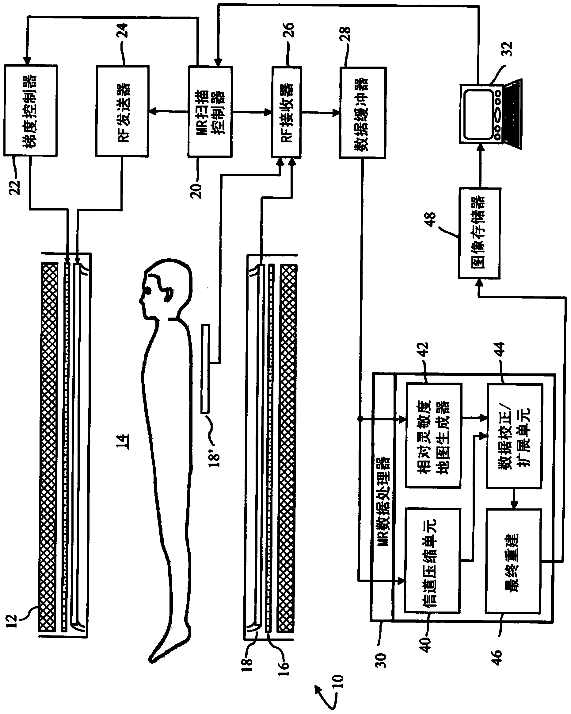
[0018] refer to figure 1 , the magnetic resonance imaging system 10 includes a main magnet 12 that generates a temporally uniform B across an examination region 14 0 field. The main magnet can be a ring or hole type magnet, a C-shaped open magnet, open magnets of other designs, and the like. A gradient magnetic field coil 16 positioned adjacent to the main magnet is used along the 0 The axis selected by the magnetic field generates a magnetic field gradient.
[0019] A radio frequency (RF) coil array, such as an integral radio frequency coil, is positioned adjacent to the examination region. The RF coil array includes a plurality of individual RF coil elements 18, or may be a birdcage type coil having a plurality of elements 18 interconnected by an end-ring RF coil structure. An array of RF coils generates radio frequency pulses for exciting magnetic resonance in aligned dipoles of a subject. In some embodiments, radio frequency coil assembly 18 is also used to detect mag...
PUM
 Abstract
Description
Claims
Application Information