Sheath-core for conveying interventional device and conveying system with sheath-core

A delivery system and device technology, applied in medical science, prostheses, heart valves, etc., can solve problems that threaten the life safety of patients, release failure of implanted devices, and different densities of wires, so as to reduce surgical risks and surgical procedures. Effects of Difficulty, Release Avoidance, and Recycling Blockage

Active Publication Date: 2013-12-11
VENUS MEDTECH (HANGZHOU) INC
View PDF16 Cites 22 Cited by
  • Summary
  • Abstract
  • Description
  • Claims
  • Application Information

AI Technical Summary

Problems solved by technology

[0005] Similarly, another example is that the Chinese patent document with publication number CN102258402A relates to a heart valve delivery system and delivery device thereof, Figure 20 It shows the state of a heart valve with a structure in the patent (that is, the artificial heart valve replacement device) when it starts to be loaded. It can be seen that the density of the wires at both ends of the heart valve 300 is obviously different. When it is fully loaded into the delivery device, as shown in Figure 21 As shown, it can be seen that although the heart valve 300 is compressed into a tubular shape, there is a large gap 601 between the lock rod and the sheath core 500, and the suspension is obvious.
[0006] Therefore, when the delivery system carries the implanted device and turns, the more sparse the load in the sheath, the easier it is to bend, especially the hanging part of the stem of the lock is easy to bend, resulting in the failure of the release of the implanted device and threatening the patient. safety of life

Method used


Image

  • Sheath-core for conveying interventional device and conveying system with sheath-core
  • Sheath-core for conveying interventional device and conveying system with sheath-core
  • Sheath-core for conveying interventional device and conveying system with sheath-core

Examples


Embodiment Construction

[0053] The present invention will be further explained below in conjunction with specific examples.

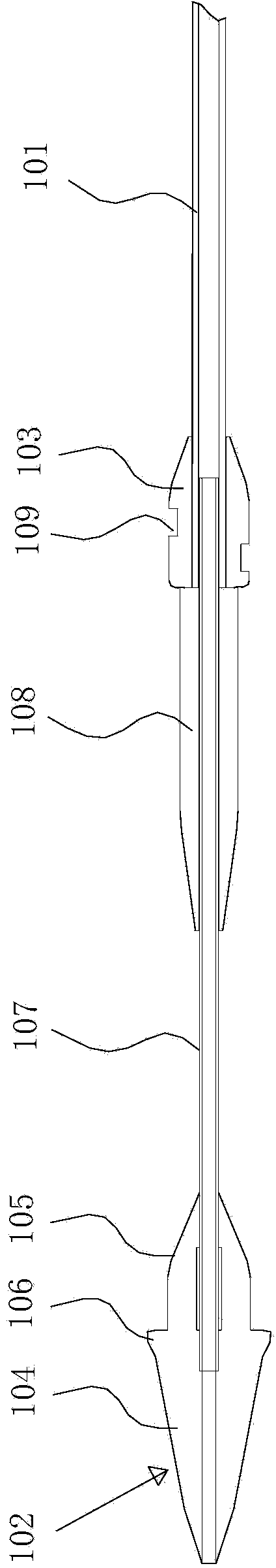
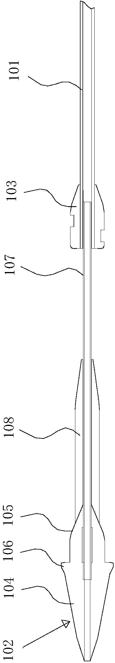
[0054] figure 1 Shown is the structure of the sheath core used for delivery of interventional instruments in the present invention, including a core tube 101 , a guide head 102 and an implantation instrument fixing head 103 .

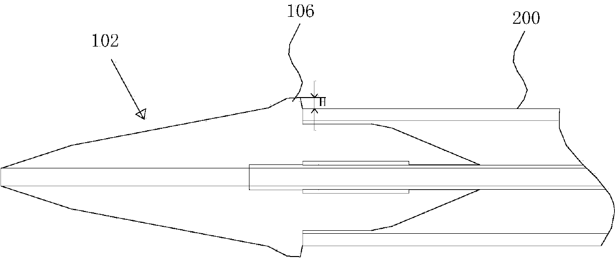
[0055] The guide head 102 is fixedly connected with the distal end of the core tube 101. The guide head 102 has a head 104 and a tail 105. The head 104 and the tail 105 of the guide head 102 are conical structures, and the head 104 has a streamlined shape. The shape can avoid scratching the inner wall of the blood vessel, and is also conducive to guiding the entire delivery system to advance along the blood vessel. The head 104 of the guide head 102 is also provided with a radial protruding ring 106 for blocking the end face of the sheath, figure 2 It shows the status diagram of the guide head when the sheath core and the sheath tube are used togeth...


PUM


Abstract

The invention discloses a sheath-core for conveying an interventional device and a conveying system with the sheath-core. The sheath-core comprises a core tube, wherein a guiding tip and an interventional device fixing tip are fixed at the far end of the core tube, a mounting section for accommodating a device to be implanted is arranged on the core tube between the guiding tip and the implanting device fixing tip; a tube wall thickening layer is arranged on the periphery of the mounting section. The conveying system comprises a sheath tube, and the sheath-core which is arranged in the sheath tube and used for conveying the interventional device. The sheath-core for an interventional operation can be used for preventing the conveying system from bending in the forwarding process, and is high in safety. According to the conveying system, the bending direction controllability of the far end of the sheath tube can be improved, and a doctor can conveniently bend the far end of the sheath tube and move the far end of the sheath tube to a target direction or site through a traction wire, so that the operation difficulty can be lowered.

Description

technical field [0001] The invention belongs to the technical field of medical instruments, and in particular relates to a sheath core for delivery of interventional instruments and a delivery system with the sheath core. Background technique [0002] Interventional surgery causes little trauma to the human body and is less invasive. It is a medical technology that has been rapidly emerging and promoted in recent years. It usually requires a special delivery system to deliver diagnostic and treatment equipment, implanted equipment, etc. to the lesion. The delivery system is mainly composed of a sheath tube, a sheath core located in the sheath tube, and an operating handle at the proximal end. During delivery, the implanted instrument is installed on the distal end of the sheath core, and the sheath tube covers the outside of the sheath core and implants the instrument. Compression, through the pre-established guide wire track, the distal end of the delivery system is punctur...

Claims


Application Information

Patent Timeline
Patent Type & Authority Applications(China)
IPC IPC(8): A61F2/24
CPCA61F2/2436
Inventor 曾敏张志飞
Owner VENUS MEDTECH (HANGZHOU) INC
Why Eureka
Try Eureka