Flash evaporation tank

A flash tank and tank technology, applied in the field of chemical equipment, can solve the problems of product loss, affecting gas quality, incomplete vapor-liquid separation, etc., and achieve the effect of less waste gas pollution, good defoaming effect, and saving raw materials.

Inactive Publication Date: 2013-12-11
天津聚贤达科技有限公司
View PDF0 Cites 5 Cited by
  • Summary
  • Abstract
  • Description
  • Claims
  • Application Information

AI Technical Summary

Problems solved by technology

This flash tank has the problem of incomplete vapor-liquid separation
It not only affects the quality of recovered gas, but also causes a certain loss of product

Method used


Image

  • Flash evaporation tank
  • Flash evaporation tank

Examples


Embodiment Construction

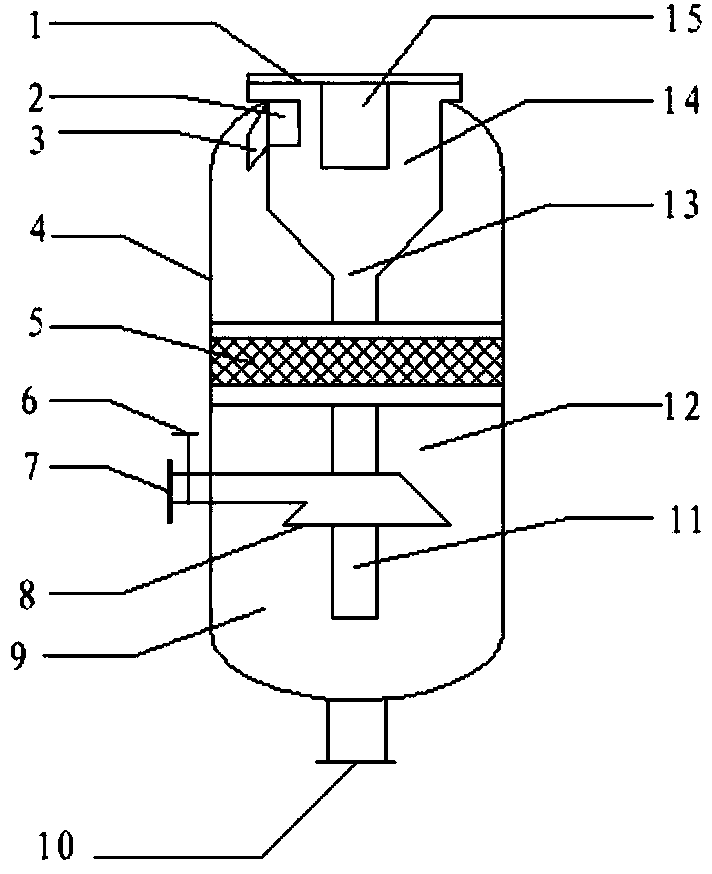
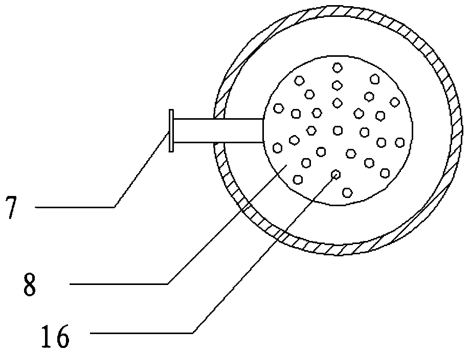
[0017] The present invention will be further described below in conjunction with the accompanying drawings. figure 1 with figure 2 They are the structural schematic diagram of the flash tank in the present invention and the sectional view of the feed pipe respectively. Such as figure 1 As shown, the flash tank includes a tank body 4 , a feed pipe 7 , a demister 5 , a separation device 13 , a gas outlet pipe 15 , and a discharge pipe 10 . The tank body 4 is made of stainless steel; the feed pipe 7 is located below the tank body 4 and extends into the inner cavity of the tank body 4. The feed pipe 7 is provided with a valve 6 and a nozzle 8, and the nozzle 8 is densely covered with nozzle holes 16. 8 Divide the inner cavity of the tank body 4 into a spray chamber 9 and an expansion chamber 12; the demister 5 is located above the feed pipe 7 and is composed of wire mesh packing; the separation device 13 is located above the tank body 4, and the separation device 13 can be Var...


PUM


Abstract

The invention relates to a flash evaporation tank. The flash evaporation tank comprises a tank body, a material charge pipe, a defoaming device, a separation device, a gas exhaust pipe and a material discharge pipe, wherein the tank body is made of stainless steel materials; the material charge pipe is positioned below the tank body and extends into an inner cavity of the tank body; the material charge pipe is provided with a valve and a sprayer; spray holes are distributed in the sprayer densely; the inner cavity of the tank body is divided into a spraying separation chamber and a volume expanding chamber by the sprayer; the defoaming device is positioned above the material charge pipe, and consists of silk net packing; the separation device is positioned above the tank body, can adopt various vapor liquid separators, and comprises a gas inlet, a separation area and a flow guide pipe; the gas exhaust pipe is positioned on the top of the tank body and extends into the separation device, is communicated with the inner part of the tank body through the separation device, and is connected with the tank body through a flange; the material discharge pipe is positioned on the bottom of the tank body. The flash evaporation tank has the advantages of good separation effect, good defoaming effect, slight waste gas pollution and raw material conservation.

Description

technical field [0001] The invention relates to a vapor-liquid separation device, in particular to a flash tank, which belongs to the field of chemical equipment. Background technique [0002] In chemical production, flash tank is a commonly used chemical equipment for vapor-liquid separation. The principle of flash evaporation is that a high-pressure liquid mixture with dissolved gas enters a low-pressure flash tank. Due to the sudden drop in pressure, the boiling point of the liquid also decreases. The liquid is separated into liquid and gas under the pressure of the pressure vessel, usually the liquid is formed into a product, and the gas is separated from the flash tank, thereby realizing the separation of vapor and liquid and the liquefaction, cooling and purification of the mixture. The flash tank provides an ideal space for the vapor-liquid separation of the mixture, and at the same time can improve the effect of the vapor-liquid separation. The traditional flash ta...

Claims


Application Information

Patent Timeline
Patent Type & Authority Applications(China)
IPC IPC(8): B01D3/06
Inventor 李玉丹郑飞飞赫川
Owner 天津聚贤达科技有限公司
Why Eureka
Try Eureka